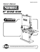
Model No. 240-3731 Owner’s Manual 9” BAND SAW QUESTION... 1•877•393•7121 You will need this manual for safety instructions, operating procedures, and warranty. Put it and the original sales invoice in a safe, dry place for future reference.
TABLE OF CONTENTS SECTION PRODUCT SPECIFICATIONS PAGE SAFETY RULES 1 Work Preparation Work Area Preparation Tool Maintenance Tool Operation ASSEMBLY 2 Unpacking Install Table Assembly Mount Band Saw Power Source Grounding Instructions Extension Cords Motor OPERATION 4 Description Safety Precautions ON/OFF Switch Replace Band Saw Blade Adjust Blade Tracking Mechanism Adjust Blade Tension Adjust Blade Guides Miter Gauge Blade Width Blade Pitch Contour Sawing Bevel Cutting MAINTENANCE 7 Cle
SAFETY RULES WARNING For your own safety, read and understand all warnings and operating instructions before using any tool or equipment. WARNING Some dust created by operation of power tool contains chemicals known to the State of California to cause cancer, birth defects or other reproductive harm. To reduce your exposure to these chemicals: work in a well ventilated area and work with approved safety equipment.
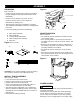
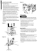
ASSEMBLY 2 Figure 2 UNPACKING Refer to Figure 1. • Check for freight damage before opening the package. If freight damage is noticed, file claim with the carrier immediately. • Check to ensure all parts are present. Contact Customer Service Center at 1-877-393-7121 immediately for missing parts. • This band saw comes mostly assembled. It requires some additional assembling, installation, and adjustment before use.
A temporary 3-prong to 2-prong grounding adapter (see Figure 5) may be used to connect this plug to a matching 2-conductor receptacle as shown in figure 5. The temporary adapter should be used only until a properly grounded outlet can be installed by a qualified electrician. ASSEMBLY may cause overheating and motor burn-out. Heavy loads require that voltage at motor terminals be no less than the voltage specified on nameplate. • Power supply to the motor is controlled by a locking rocker switch.
OPERATION 4 DESCRIPTION • This 9” band saw has welded steel frame and cast iron table. It is designed to cut woods, plastics, and nonferrous metals. The solid durable structure will withstand continuous heavy-duty workloads for many years to come. • This band saw is equipped with miter gauge for various precision operations. • The versatile adjustable table can be easily tilted to any angle between 0 and 45 degrees. • Simple and quick saw blade tension adjustment.
Figure 7 Tension Knob Blade Tension Lever Tracking Window Upper Guide Adjusting Knob Tracking Knob Door Latch Tracking lock nut Blade Guide Lock Knob Figure 8 Blade Guard Panel ADJUST BLADE TRACKING MECHANISM Refer to Figure 7 OPERATION • Turn the blade guide knob, located below the upper door latch, to lower the Upper blade guide completely. • Carefully unsnap and remove the blade guard panel. • Release the table insert from the cast iron table.
OPERATION 6 ADJUST BLADE GUIDES Refer to Figure 9 to 11 • Blade guides should not be in contact with the blade when not in operation. • Adjust the blade guides after the blade tracking and blade tension have been properly adjusted. • The blade guide supports the blade with bearings on the real and guide pins on both sides. They all should be adjusted to be 0.016” inches away from the blade. Use feeler gauge for accurate measurement.
OPERATION CONTOUR SAWING • Contour cutting is guiding workpiece free-handed to produce curved shapes. • Turn the workpiece carefully so the blade follows without twisting. • Use a narrower blade to cut abrupt curves or make relief cuts. BEVEL CUTTING • Beveled cutting is to tilt saw table for the desired degree. • Loosen locking handle to unlock table. • Rotate knob to tilt table to desired position. • Lock table by tightening locking handle.
8 TROUBLESHOOTING SYMPTON POSSIBLE CAUSE(S) SOLUTIONS Motor will not start 1. Low voltage 2. Short circuit in line cord or plug 1. Check power supply for proper voltage 2. Inspect line cord and plug for faulty insulation or shorted connection 3. Inspect connection on motor. 4. Inspect connection on motor 3. Short circuit in motor 4. Open circuit or loose connection in motor 5. Incorrect fuses or circuit breakers 6. Defective switch 7. Defective capacitor Motor stalls or fails to reach full speed 1.
9” BAND SAW PARTS ILLUSTRATION 9
9" BAND SAW PARTS LIST 10 Key No. 1 2 3 4 4.1 5 6 7 8 9 10 11 12 13 14 15 16 17 18 19 20 20.1 21 22 23 23.1 24 25 26 27 28 29 30 31 32 33 34 35 36 37 37.1 38 39 39.1 39.2 40 41 42 43 43.1 44 45 45.1 46 47 48 49 50 51 Part No.
9” BAND SAW PARTS LIST Key No. Part No. 105 106 106.1 107 107.1 108 109 110 111 112 113 114 116 117 118 119 120 121 BS900120 BS900121 BS900122 BS900123 BS900124 BS900125 BS900126 BS900127 BS900128 BS900129 BS900130 BS900131 BS900132 BS900133 BS900134 BS900135 BS900136 BS900137 Description Specification Qty TAP SCREW Ø4*8L PINION SET SCREW M4*4L BRACKET WASHER Ø6 HANDLE HEX SOC HD SCR M5×P0.8×10L PLUG BLADES 62’L*6mmW*0.
13 PERFORMAX™ 9” BAND SAW 30-DAY MONEY BACK GUARANTEE: This PERFORMAX™ brand power tool carries our 30-Day Money Back Guarantee. If you are not completely satisfied with your PERFORMAX™ brand power tool for any reason within thirty (30) days from the date of purchase, return the tool with your original receipt to any MENARDS® retail store, and we will provide you a refund – no questions asked.
Menard, Inc.