
Assembly Instructions

1. Refer to photo above and to the Assem-
bly Diagrams and Parts Lists at end of this
manual.
2. Some assembly is required. Reference
paragraph M on page 3. When unpack-
ing the product it is recommended that the
product be slid out of the side of the box,
rather than lifted from the box. While un-
packing, always grip the main frame and
not the table; this will prevent the table
from inadvertantly opening up.
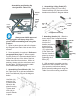
3. Assembling Front Wheels (20). Set
the Table Cart on its side and assemble
both Front Wheels (20) per the diagram
below.
Use Bolt (16)
and Nut (14)
to attach each
Wheel to the
wheel housing.
Tighten both
Nuts (14) to
secure Wheels
in place.
Assembling and Setting Up
the Hydraulic Table Cart
4. Assembling Lifting Pedal (27).
Slide Lifting Pedal (27) into Lifting
Pedal Assembly (30) and secure with
hardware as shown in diagram below.
5. Attaching Handle (21). Slide the
lower ends of the U-shaped tubular
Handle (21)
into the two
handle receptacles
located in the
Base Assembly
(17) at the back
of the Table Cart.
Secure Handle in
place by securely
tightening the 2
Bolts (47).
6. With assembly complete, test the
operation of the Hydraulic Table Cart
(see operation instructions below),
before actually loading and using the
Table Cart under working conditions.
Always wear ANSI approved
safety goggles and heavy duty work
gloves when assembling and using this
product.
Front
Wheels
(20)
Lifting
Pedal
(27)
Safety Bar
(7)
Bolt
Washer
Washer
Nut
12
Lifting
Pedal
Lifting Pedal Assembly
Handle
(21)
Handle
(21)
Bolt
(47)
Base
Assembly
(17)
Back Caster
Assembly (19)
Oil Plug
(P04)