0’’ SLIDING COMPOUND MITER SAW 240-3689 OPERATOR’S MANUAL CAUTION: To Reduce The Risk Of Injury, User Must Read And Understand Operator’s Manual. Save These Instructions For Future Reference. For questions / comments, technical assistance or repair parts – Please Call Toll Free: 1-866-858-2664. (M-F 8:30am-5:00pm Est.
TABLE OF CONTENTS Safety Symbols. . . . . . . . . . . . . . . . . . . . . . . . . . . . . . . . . . . . . . . . . . . . . . . . . . . . . . . . . . Page 2 Safety Instructions. . . . . . . . . . . . . . . . . . . . . . . . . . . . . . . . . . . . . . . . . . . . . . . . . . . . . . . Page 3 Overview/Specifications . . . . . . . . . . . . . . . . . . . . . . . . . . . . . . . . . . . . . . . . . . . . . . . . . Page 12 Assembly . . . . . . . . . . . . . . . . . . . . . . . . . . . . . . . . . . . . . . . . .
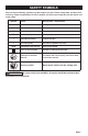
SAFETY SYMBOLS Some of these following symbols may be used on this tool. Please study them and learn their meaning. Proper interpretation of these symbols will allow you to operate the tool better and more safely.
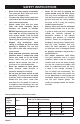
SAFETY INSTRUCTIONS The purpose of safety symbols is to attract your attention to possible dangers. The safety symbols, and the explanations with them, deserve your careful attention and understanding. The symbol warnings do not, by themselves, eliminate any danger. The instructions and warnings they give are no substitutes for proper accident prevention measures.
SAFETY INSTRUCTIONS WARNING: Safety symbols in this Instruction Manual are used to flag possible dangers. The safety symbols and their explanations require your full understanding. The safety warnings do not, by themselves, eliminate any danger, nor are they substitutes for proper accident prevention measures. WARNING: This Safety Alert Symbol indicates caution, warning, or danger. Failure to obey a safety warning can result in serious injury to yourself or others.
SAFETY INSTRUCTIONS • • When operating a power tool outdoors, use an extension cord suitable for outdoor use. Use of a cord suitable for outdoor use reduces the risk of electric shock. If operating a power tool in a damp location is unavoidable, use a ground fault circuit interrupter (GFCI) protected supply. Use of an GFCI reduces the risk of electric shock. • • PERSONAL SAFETY • • • • • • Stay alert, watch what you are doing and use common sense when operating a power tool.
SAFETY INSTRUCTIONS • • • Keep cutting tools sharp and clean. Properly maintained cutting tools with sharp cutting edges are less likely to bind and are easier to control. Use the power tool, accessories and tool bits etc. in accordance with these instructions, taking into account the working conditions and the work to be performed. Use of the power tool for operations different from those intended could result in a hazardous situation.
SAFETY INSTRUCTIONS • • • • • • • Do not use the saw until the table is clear of all tools, wood scraps, etc., except for the workpiece. Small debris or loose pieces of wood or other objects that contact the revolving blade can be thrown with high speed. Cut only one workpiece at a time. Stacked multiple workpieces cannot be adequately clamped or braced and may bind on the blade or shift during cutting. Ensure the miter saw is mounted or placed on a level, firm work surface before use.
SAFETY INSTRUCTIONS • • • • • • • • • • • correct direction. The teeth on the blade should point in the direction of rotation as marked on the saw. Tighten all clamp handles, knobs and levers prior to operation. Loose clamps can cause parts or the workpiece to be thrown at high speeds. Be sure all blade and blade clamps are clean, recessed sides of blade clamps are against blade and arbor screw is tightened securely.
SAFETY INSTRUCTIONS • • Never leave tool running unattended. Turn power off. Don’t leave tool until it comes to a complete stop. To reduce the risk of injury, return the saw head to the full rear position after each crosscut operation. Always make sure that the miter table and head assembly (bevel function) are locked in position BEFORE operating your saw. Lock the miter table by securely tightening the miter locking handle.
SAFETY INSTRUCTIONS • • If the supply cord of this power tool is damaged, it must be replaced by a specially prepared supply cord available through the service organization. Save these instructions. Refer to them frequently and use them to instruct others who may use this tool. If someone borrows this tool, make sure he or she has these instructions also.
SAFETY INSTRUCTIONS 14. No-Hands Zone: The area between the marked lines on the left and right side of the miter-table base. This zone is identified by No-Hands Zone symbols inside the lines marked on the miter table base. 15. Non-through Cut: Any cutting operation where the blade does not extend completely through the thickness of the workpiece. 16. Revolutions Per Minute (RPM): The number of turns completed by a spinning object in one minute. 17.
OVERVIEW Switch Dust Bag Lower Blade Guard Work Clamp Mounting Hole Sliding Fence Table Insert Lower Fence Extension Bar Miter Stop Locking Lever Miter Locking Knob Depth Adjustment Screw Spindle Lock Lock-down Pin Slide-Rail Lock Knob Table Miter Scale Bevel Scale Base Bevel Lock Knob Page 12
SPECIFICATIONS Motor 120V~, 60Hz, 15A Speed 5000 RPM (no load) Blade 10" (25.4 cm) (40-tooth) Arbor size 5/8" (15.9 mm) Cutting capacity 3-1/2’’X12-3/8’’, miter 0°, bevel 0° 3-1/2’’X8-7/16’’, miter 45°, bevel 0° 1-9/16’’X12-3/8’’, miter 0°, bevel 45° 1-9/16’’X8-7/16’’, miter 45°, bevel 45° Weight 36 lb. 5 oz.
ASSEMBLY CONTENTS WARNING: If any part is broken or missing, DO NOT operate the tool until the broken or missing part is replaced. Failure to do so could result in possible serious injury. WARNING: Do not attempt to modify this tool or create accessories not recommended for use with this tool. Any such alteration or modification is misuse and could result in a hazardous condition leading to possible serious injury.
OPERATION INTENDED USE 3. This miter saw is designed for wood cutting applications. DO NOT use under wet conditions or in presence of flammable liquids or gases. DO NOT let children come into contact with the tool. Supervision is required when inexperienced operators use this tool. 4. Tighten the screw (1) to lock the work clamp. Rotate the clamp knob clockwise to clamp the workpiece and rotate the knob counterclockwise to release the pressure. Lock the screw (2) before working. FIG.
OPERATION INSTALL EXTENSION BARS (FIG.4) Extension bars have been provided for both the left and the right side of the saw. 1. Remove the screw from the end of the extension bar. 2. Insert the ends of extension bar into the holes in the sides of the base. 3. Replace screw and tighten to secure the extension bar in place. 4. Repeat for the other extension bar. 5.
OPERATION MITER SCALE (FIG.6) FIG. 6a Hole Miter Lever FIG. 6b Miter Locking Knob This tool is carefully adjusted and aligned at the factory, but rough handling may have affected the alignment. If your tool is not aligned properly, perform the following as needed. 1. 2. 3. Detent Slot Screw locking knob counterclockwise. Move the table while lifting up on the miter stop locking lever to align the indicator to the desired degree. 3.
OPERATION FIG. 7b BEVEL STOP ADJUSTMENT (FIG.8) Lower Fence Hex-head Bolts This tool is carefully adjusted and aligned at the factory, but rough handling may have affected the alignment. If your tool is not aligned properly, perform the following as needed. 90° (0°) bevel adjustment FIG. 8a 1. 2. 3. Unplug the saw. Set the bevel and miter angles to 0°. Lower and lock the saw arm in the “DOWN” position. 4.
OPERATION 3. If the blade is not 90° square with the table, loosen the bevel lock knob, put a 4 mm hex wrench into the hole located in the left side end of the arm holder, turn the hex screw clockwise or counterclockwise to make the blade square to the table. 4. Tighten bevel lock knob when alignment is achieved. 90° bevel pointer adjustment Bevel FIG. 8c Indicator FIG.
OPERATION To lock: Place the cutting head at the lowest position. Secure the position and push the lock-down pin into the locking position. Please note, if there is any cutting depth setting, the lock-down pin may not work. Release the cutting depth limitation by rotating the depth adjustment screw counterclockwise, and then lock the cutting head. FIG. 10b UNLOCK THE SLIDE RAIL (FIG.9) The slide-rail lock knob is located on the upper side of the slide rail.
OPERATION CHOP CUTS (FIG.11) FIG. 11 2. 3. 4. 5. 6. Chop cuts are used mainly for narrow pieces. 1. 2. 3. 4. 5. 6. 7. 8. Unplug the saw. Slide the head assembly to the rear as far as it will go. Tighten the slide-rail locking knob. Plug the saw into an electrical socket. Properly position the workpiece. Make sure the workpiece is clamped firmly against the table and the fence. Use a clamping position that does not interfere with the cutting operation.
OPERATION BEVEL CUT (FIG.14) FIG. 12b A bevel cut is a cut made across the grain of the workpiece with the blade at an angle to the workpiece. A straight bevel cut is made with the miter table set at the 0° position and the saw arm set at a bevel angle between 0° and 45° left. 1. MITER CUT (FIG.13) FIG. 13 Pull out extension bars if the workpiece is relatively long. 2. Loosen the bevel locking knob and tilt the saw arm to the desired bevel angle, as indicated on the bevel scale.
OPERATION COMPOUND CUTS (FIG.15) 1. FIG. 15 2. 3. 4. 5. A “compound cut” is a cross-cut made with the blade both at a miter angle and at a bevel angle. Because it may take several tries to obtain the desired compound angle, perform test cuts on scrap material before making your cut. 1. 2. 3. 4. 5. If the cutting process is interfered by the sliding fence, just remove the sliding fence (refer to “INSTALL/REMOVE THE SLIDING FENCE” section). Properly position workpiece.
OPERATION CUTTING WARPED MATERIAL (FIG.17) FIG. 17a CUTTING BASE MOULDING (FIG.18) Top View FIG. 18 Fence Miter at 0°, Bevel at 45° Molding Lying Flat On Miter Table (Before Clamping) Miter Saw Molding Standing Up Against Fence (Before Clamping) Fence Miter Saw Miter at 45°, Bevel at 0° Right FIG. 17b Top View Base moldings and many other moldings can be cut on a miter saw. The setup of the saw depends on the base molding characteristics and applications, as shown.
OPERATION CUTTING CROWN MOULDING (FIG.19) Your miter saw is ideal for cutting crown molding. To fit properly, crown molding must be compound-mitered with extreme accuracy. To fit flat against the ceiling and wall, the sum of the angles of the crown molding’s two connecting surfaces must equal 90°. Crown molding has a high top rear spring angle (the section that fits flat against the ceiling) of 52° and a bottom rear spring angle (the section that fits flat against the wall) of 38°. FIG.
MAINTENACE WARNING: When servicing, use only identical replacement parts. Use of any other parts may create a hazard or cause product damage. WARNING: To avoid serious personal injury, always unplug the power from the product when cleaning or performing any maintenance. Periodic maintenance allows for long life and trouble-free operation. A cleaning, lubrication and maintenance schedule should be maintained. As a common preventive maintenance practice, follow these recommended steps: 1.
MAINTENACE 1. First unplug the saw before inspecting or replacing brushes. 2. Replace both carbon brushes when either has less than 1/4” (6 mm) of carbon remaining, or if the spring or wire is damaged or burned. 3. Using a slotted screwdriver, remove the black plastic cap on each side of the motor housing, and carefully withdraw the spring-loaded brush assemblies. Keep brushes clean and sliding freely in their guide channels.
MAINTENACE 3. 4. 5. 6. 7. 8. guard. Make sure that the blade teeth are pointing downward. Place the outer flange against the blade and on the arbor. Thread the blade bolt onto the arbor in a counterclockwise direction. Place the phillips screwdriver into the blade bolt. Press the spindle-lock button, holding it in firmly while turning the blade counterclockwise. When spindle lock engages, continue to press it in while tightening the arbor screw securely.
TROUBLESHOOTING PROBLEM POSSIBLE CAUSE SOLUTION Brake does not stop blade within 10 seconds. 1. Motor brushes not sealed or lightly sticking. 1. Inspect/clean/ replace brushes. See MAINTENANCE section. 2. Motor brake overheated from use of defective or wrong size blade or rapid ON/OFF cycling. 2. Use a recommended blade. 3. Arbor screw is loose. 3. Retighten the arbor screw. Motor does not start. Brush is worn. Replace brushes. See MAINTENANCE section.
10’’ Sliding Compound Miter Saw WARRANTY 30-DAY MONEY BACK GUARANTEE: This PERFORMAX® brand power tool carries our 30-Day Money Back Guarantee. If you are not completely satisfied with your PERFORMAX® brand power tool for any reason within thirty (30) days from the date of purchase, return the tool with your original receipt to any MENARDS® retail store, and we will provide you a refund – no questions asked.
© 2019 Menard, Inc.