
Use And Care Manual


Page 17
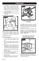
MITER SCALE (FIG.6)
FIG. 6a
Miter Lever
Hole
FIG. 6b
Miter-angle
Indicator
Screw
Detent Slot
Miter Stop
Locking
Lever
Miter
Locking
Knob
To install the miter lever:
The miter lever is put aside from the miter
saw during transport. Before operation,
align the miter lever with the hole on the
front of the miter saw, and then rotate the
miter lever clockwise to screw the lever onto
the miter saw.
To adjust miter angles:
The sliding compound miter saw scale can
be easily read, showing miter angles from 0°
to 45° to the left, and 0° to 45° to the right.
The miter saw table has nine common angle
settings with positive stops at 0°, 15°, 22.5°,
31.6° and 45°. These positive stops position
the blade at the desired angle quickly and
accurately.
1. Unlock the table by turning the miter
OPERATION
locking knob counterclockwise.
2. Move the table while lifting up on the
miter stop locking lever to align the
indicator to the desired degree.
3. If the desired angle is one of the nine
positive stops, release the miter stop
locking lever, make sure the lever snaps
into the detent slot, and then secure
by tightening the miter locking knob
clockwise.
4. If the desired angle is not one of the nine
positive stops, simply lock the table
into desired angle position by turning
the miter locking knob in the clockwise
direction.
Miter-angle indicator adjustment
This tool is carefully adjusted and aligned
at the factory, but rough handling may have
affected the alignment. If your tool is not
aligned properly, perform the following as
needed.
1. Move the table to the 0° positive stop.
2. Loosen the screw that holds the
indicator with a cross-head screwdriver.
3. Adjust the indicator to the 0° mark and
retighten the screw.
ADJUST THE FENCE
SQUARENESS (FIG.7)
FIG. 7a
Carpenter’s
Square