
Use And Care Manual


Page 18
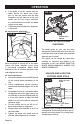
FIG. 7b
Lower
Fence
Hex-head
Bolts
1. Unplug the saw.
2. Set the bevel and miter angles to 0°.
3. Lower and lock the saw arm in the
“DOWN” position.
4. Place the heel of a carpenter’s square
(available separately) against the blade
and the ruler of the square against the
fence (Fig.7a).
5. If the blade is not 90° to the fence,
completely unscrew the locking screw of
the sliding fence and remove the sliding
fence (refer to “INSTALL/REMOVE THE
SLIDING FENCE” section).
6. Loosen the four hex-head bolts (Fig.7b)
on both sides of the lower fence with a
5 mm hex wrench and rotate the lower
fence until the blade is square to the
lower fence. Retighten the hex-head
bolts. Remount the sliding fence.
NOTICE:
• Be sure to rest the square against the
body of the blade, and not against the
teeth of the blade.
• If the saw has not been used recently,
verify that the blade is square to the
fence, and readjust if necessary.
BEVEL STOP ADJUSTMENT
(FIG.8)
This tool is carefully adjusted and aligned
at the factory, but rough handling may have
affected the alignment. If your tool is not
aligned properly, perform the following as
needed.
90° (0°) bevel adjustment
FIG. 8a
Carpenter’s
Square
FIG. 8b
Nut
Bevel Lock
Knob
Hole
Bolt
1. Loosen bevel lock knob. Tilt the cutting
arm completely to the right. Tighten the
bevel lock knob.
2. Place a combination square on the
table with the ruler against the table and
the heel of the square against the saw
blade.
OPERATION