
Use And Care Manual


Page 19
3. If the blade is not 90° square with the
table, loosen the bevel lock knob,
put a 4 mm hex wrench into the hole
located in the left side end of the arm
holder, turn the hex screw clockwise
or counterclockwise to make the blade
square to the table.
4. Tighten bevel lock knob when alignment
is achieved.
90° bevel pointer adjustment
FIG. 8c
Screw
Bevel
Indicator
When the blade is exactly 90° to the table,
loosen the bevel indicator screw using
a cross-head screwdriver. Adjust bevel
indicator to the “0” mark on the bevel scale
and retighten the screw.
45° bevel adjustment
1. Loosen the bevel lock knob (FIG.8b) and
tilt the cutting head completely to the
left.
2. Using a combination square, check to
see whether the blade angle is 45° to the
table.
3. If the blade is not at 45° to the miter table,
tilt the pivot arm to the right, loosen the
nut (FIG.8b) on the bolt (FIG.8b) and use
a 5 mm hex wrench to adjust the bolt
depth in or out to increase or decrease
the bevel angle.
4. Tilt the cutting arm to the left to 45°
bevel and recheck for alignment.
5. Repeat steps until the blade is at 45° to
the miter table.
6. Tighten the bevel lock knob and nut
(FIG.8b) when alignment is achieved.
FIG. 8d
Combination
Square
GUARD ACTUATION AND
CHECKING
The blade guard on your saw has been
designed to automatically raise when the arm
is brought down and to lower over the blade
when the arm is raised.
The guard can be raised by hand when
installing or removing saw blades or for
inspection of the saw. NEVER RAISE THE
BLADE GUARD MANUALLY UNLESS THE
SAW IS TURNED OFF.
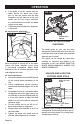
UNLOCK AND LOCK THE
CUTTING HEAD (FIG.9)
FIG. 9
Lock-down
Pin
Slide-rail Lock
Knob
Depth Adjustment
Screw
To unlock: Press and lightly hold down the
cutting head. Pull out the lock-down pin to
release the cutting head. The cutting head
should freely move up.
OPERATION