
Use And Care Manual


Page 22
OPERATION
FIG. 12b
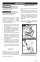
MITER CUT (FIG.13)
FIG. 13
1. Loosen miter locking knob. While
holding the miter locking knob, lift miter
stop locking lever and move the saw to
the desired angle. Tighten miter locking
knob. Refer to “MITER SCALE” section
for instructions.
2. Properly position workpiece. Make sure
workpiece is clamped firmly against the
table. Use clamping position that does
not interfere with operation. Before
switching on, lower head assembly to
make sure clamp clears guard and head
assembly.
3. Follow procedures for either chop cuts
or slide cuts.
4. Wait until blade comes to a complete
stop before returning head assembly
to the raised position and/or removing
workpiece.
BEVEL CUT (FIG.14)
A bevel cut is a cut made across the grain
of the workpiece with the blade at an angle
to the workpiece. A straight bevel cut is
made with the miter table set at the 0°
position and the saw arm set at a bevel
angle between 0° and 45° left.
1. Pull out extension bars if the workpiece
is relatively long.
2. Loosen the bevel locking knob and tilt
the saw arm to the desired bevel angle,
as indicated on the bevel scale. The
blade can be positioned at any angle
from a 90° straight cut (0° on the scale)
to a 45° left.
3. Tighten the bevel locking knob to secure
the saw arm in position.
4. Follow procedures for either chop cuts
or slide cuts.
NOTICE: Be sure to move sliding fence
away from the blade to avoid cutting into
the fence when bevel cutting. The sliding
fence may need to be removed when
preforming extreme bevel cuts and most
compound cuts.
FIG. 14