UltraPort Serial Adaptors User Guide Part number: 5500152-22 Date: 11 September 2008 Navigating around this manual Using this on-line manual. See page 5. Fast Contents. See page 7. Contents. See page 8. Index. See page 155.
Copyright statement This document must not be reproduced in any way whatsoever, either printed or electronically, without the consent of: Perle Systems Limited 60 Renfrew Drive Markham, Ontario, Canada L3R 0E1 Perle reserves the right to make changes without further notice, to any products to improve reliability, function or design. JETSTREAM, JETSTREAM4000, JETSTREAM8500 and LANSTREAM2000 are trademarks of Perle Systems Limited.
FCC Note The products described in this manual have been found to comply with the limits for a Class A digital device, pursuant to Part 15 of the FCC rules. These limits are designed to provide reasonable protection against harmful interference when the equipment is operated in a commercial environment. This equipment generates, uses and can radiate radio frequency energy and, if not installed and used in accordance with the instructions in this Guide, may cause harmful interference to radio communications.
UltraPort Serial Adaptors User Guide About this manual Purpose of this manual This manual tells you how to install, configure and use the Perle UltraPort, UltraPort SI, and UltraPort Express serial adaptor cards, cabling hardware, associated drivers and utilities. Who this manual is for This manual is aimed at users who want to add extra serial ports to their system using UltraPort serial adaptor cards.
Using this on-line manual The following is a brief guide to using this manual on-line.
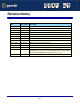
Revision history Date Part number Description June 2003 5500152-10 First issue of the UltraPort user manual. October 2003 5500152-11 Support for UltraPort2 and UltraPort8i adapter cards. February 2004 5500152-12 Updated the UltraPort for Linux installation. May 2004 5500152-13 Support for Linux 2.6 kernels. June 2004 5500152-14 Support for UltraPort SI adapter cards. November 2004 5500152-15 Support for Windows 95/98 on Ultraport SI adapter cards.
UltraPort Serial Adaptors User Guide Fast Contents ABOUT THIS MANUAL ........................................................... 4 REVISION HISTORY ............................................................... 6 FAST CONTENTS .................................................................. 7 CONTENTS ........................................................................... 8 CHAPTER 1 INTRODUCTION .................................................. 13 CHAPTER 2 INSTALLING DRIVERS AND HOST CARDS .....
UltraPort Serial Adaptors User Guide Contents ABOUT THIS MANUAL ............................................................ 4 Purpose of this manual ..................................................................................4 Who this manual is for ...................................................................................4 Using this on-line manual ..............................................................................5 Document navigation ..........................................
Installing under Windows NT .......................................................................33 Installing under Windows 2000/XP/Server 2003/Vista/Server 2008 .......34 General setup procedure for Windows 2000/XP/Server 2003/Vista/ Server 2008 ..............................................................................................35 Installing device drivers and utilities onto your system .............................36 Adding additional cards and/or updating drivers.............................
Installing under Linux .....................................................................................87 General installation procedure for Linux ...................................................87 Installing Drivers onto your system ...........................................................87 Uninstall Patch Versions ................................................................................ 88 Install from Source RPM ...........................................................................
Connector box and cable pinouts ...............................................................118 RJ45 10-pin to DB25 converter.................................................................119 RJ45 10-pin to DB9 converter...................................................................120 RJ45 10-pin to RJ45 SPEED converter ....................................................121 RJ45 10-pin to RJ45 Digi converter ..........................................................
APPENDIX D : CONTACTING PERLE 151 Making a technical support query ...............................................................151 Who to contact ..........................................................................................151 Information needed when making a query................................................152 Making a support query via the Perle web page.......................................153 Repair procedure .......................................................................
UltraPort Serial Adaptors User Guide Chapter 1 Introduction You need to read this chapter if you want to... You need to read this chapter if you want an introduction to the Perle UltraPort, UltraPort SI, and UltraPort Express serial adaptor cards, driver software and configuration utilities.
About the UltraPort, UltraPort SI, and UltraPort Express Serial Adaptor cards The UltraPort Serial Adaptor cards are multi-port cards which provide extra serial ports for EIA-232, EIA-422 and EIA-485 peripherals. These cards plug into your PC servers and provide 1,2, 4, 8 or 16 high speed ports suitable for remote access, data collection, point of sale or any other EIA-232, EIA-422, or EIA-485 applications.
Connection accessories The connector box or cable required for the UltraPort products you are using depends on the number of ports and product type.
UltraPort Serial Adaptors User Guide Chapter 2 Installing drivers and host cards You need to read this chapter if you want to... You need to read this chapter if you want to install UltraPort, UltraPort SI, and UltraPort Express serial adaptor cards, associated hardware and software. This chapter provides information about installing and configuring UltraPort, UltraPort SI, and UltraPort Express serial adaptor cards.
Before you start Before you install your UltraPort, UltraPort SI, and UltraPort Express host cards and software, note that the procedure for installing and configuring UltraPort and UltraPort SI, UltraPort Express serial adaptor cards varies for different operating systems.
Downloading drivers from the Perle web site You can install the UltraPort driver and utility software from the Perle web site. To do this proceed as follows: 1. On your PC, start the Internet browser you want to use. 2. Within your Internet browser window, select the software directory using the following URL: http://www.perle.com/downloads Note In the event of any problems contact your System Administrator or Internet Service provider for assistance. 3. Change to the software directory.
Installing under Windows 95 and 98 This section tells you how to install UltraPort and UltraPort SI only host cards, software drivers and utilities under the Windows 95 and Windows 98 operating systems and includes the following: • General installation procedure for Windows 95 and 98 on page 20 • Installing device drivers and utilities on page 21 • Configuring serial ports on page 25 • Removing drivers and utilities from your system on page 31.
General installation procedure for Windows 95 and 98 The general procedure for installing UltraPort and UltraPort SI only cards under the Windows 95/98 operating systems is as follows: 1. Install any UltraPort and UltraPort SI cards and cables or connector boxes you require into your system. See Installing host cards and cable accessories on page 95. 2. Using the Windows Found New Hardware Wizard, install the UltraPort or UltraPort SI device driver software.
Installing device drivers and utilities To install or enable the UltraPort and UltraPort SI device drivers on your system proceed as follows: 1. Turn on your PC and if required, log in.
2. Proceed by clicking Next and the following Add New Hardware Wizard window will appear: 3.
4. Inset the Perle CD and check the Specify a location check box. Now either browse to, or type in the following path d:\driversultraport\win9x\x.yy. Where x.yy is the windows 95/ 98 driver version number.
5. Proceed by clicking Next and the final Add New Hardware Wizard window will appear as below: 6. Proceed by clicking Finish. Windows will now copy all the files needed for the device driver. After the driver installation is complete, the driver will automatically find all of the serial ports associated with the UltraPort or UltraPort SI card. A series of New Hardware Found messages will be temporarily displayed for every port found. Installation of the device drivers and utilities is now complete.
Configuring serial ports To configure UltraPort or UltraPort SI serial ports proceed as follows: 1. In the windows desktop, click on the Start button and select Settings > Control panel. The control panel window is now displayed. 2. In the control panel window, double click on the System icon. The System Properties tabbed window is displayed. Hint You can also display the System Properties tabbed window by right clicking on the My Computer icon on your desktop and selecting the Properties menu option.
3. In the System Properties tabbed window, click on the Device Manager tab. The Device Manager page is now displayed. 4. In the Device Manager page, double click on the device whose properties you wish to view. The properties tabbed window for the selected device is now displayed.
5. In the properties window, click on the Port Settings tab. The Settings page is now displayed. 6. In the Port Settings page, select the configuration values you want and either click on the OK button or click on the FIFO Settings tab to display FIFO configuration settings for the device driver.
7. The FIFO Settings page is now displayed as shown in the next picture Selects the port name for a given device. Allows you to select the default port name or change it to any unused port name. Default display is the currently assigned port name. 8. In the FIFO Settings page, select the configuration values you want and either click on the OK button or, if the COM port belongs to a UltraPort SI card, then you can click on the Protocol Settings tab to access the software switchable interface modes.
9. The Protocol Settings page is now displayed as shown in the next picture 10.In the Protocol Settings page, select the configuration values you want and click on the OK button. Re-configuration of ports is now complete. Protocol Type: The valid software switchable protocol types are EIA-232, EIA-422, EIA-485 Full Duplex and EIA-485 Half Duplex. Each port on the UltraPort SI are independent of each other and therefore you may select different protocols per serial port.
Line Termination: The line termination parameter is not changeable by the user in EIA-232 mode. However both EIA-422 and EIA-485 modes are defaulted to disabled but can be enabled by the user if needed. EIA-485 HDX Local Echo: Local echo by default is on. This parameter applies only to EIA-485 half duplex mode. All characters will be echoed to the user and transmitted across the serial ports.
Removing drivers and utilities from your system To remove drivers and utilities from your system proceed as follows: 1. In the windows desktop, click on the Start button and select Settings > Control panel. The control panel window is now displayed.
2. In the control panel window, double click on the System icon. The System Properties tabbed window is now displayed as shown in the next picture. 3. In the System Properties tabbed window, click on the Device Manager tab The Device Manager page is now displayed. 4. In the Device Manager page, click on the Perle Multi-function adapter that you wish to remove, highlighting it then press the Remove button. The selected device is now removed from the system.
Installing under Windows NT The procedure for installing and configuring host cards, drivers software and associated utilities for the Windows NT operating system is as follows: Note The Perle PortDirector software contains drivers for the UltraPort and UltraPort SI host cards only. You will need to install the PortDirector for Windows NT on your system in order to use the UltraPort and UltraPort SI host cards. See the PortDirector user guide part number 5500028 for further details. 1.
Installing under Windows 2000/XP/Server 2003/Vista/ Server 2008 This section describes how to install the UltraPort, UltraPort SI, and UltraPort Express driver software under Microsoft Windows 2000, XP, Server 2003, Vista, or Server 2008.
General setup procedure for Windows 2000/XP/Server 2003/Vista/Server 2008 The general procedure for installing UltraPort, UltraPort SI, and UltraPort Express cards under the Windows 2000, XP, Server 2003, Vista, or Server 2008 operating systems is as follows: 1. Install any UltraPort and cards and cables or connector boxes you require into your system. See Installing host cards and cable accessories on page 95. 2. Install the UltraPort, UltraPort SI, or UltraPort EXPRESS device driver software.
Installing device drivers and utilities onto your system To install or enable the UltraPort, UltraPort SI, and UltraPort Express device drivers on your system proceed as follows: 1. Turn on your PC and if required, log in. If you have installed any new UltraPort cards, a Found New Hardware message is briefly shown followed by the Found New Hardware wizard as shown in the pictures. 2. In the Found New Hardware wizard click the Cancel button. 3.
4. Unzip the driver zip file to a local directory. We recommend that you use the pserial-setup-.exe file, which will launch the installation wizard, to install the UltraPort/UltraPort SI/UltraPort Express driver. 5. Double-click the pserial-setup-.
6. During the installation, you may get a Windows Logo message. Click Continue Anyway when these appear. Note If you are installing an unsigned driver, you may have to click through the Found New Hardware wizard for every UltraPort port on your system. Your UltraPort/UltraPort SI/UltraPort Express driver installation is now finished.
Configuring serial ports To configure UltraPort and UltraPort SI and UltraPort Express serial ports under Windows 2000, XP, Server 2003, Vista, or Server 2008 proceed as follows: 1. In the Windows desktop, click on the Start button and select Settings > Control Panel The control panel window is now displayed. 2. In the Control Panel window, click on the System icon. The System Properties tabbed window is now displayed. 3. In the System Properties window, click on the Hardware tab.
5. In the Device Manager window, click on the Multiport serial adapters icon to display the currently installed devices. 6. In the Device Manager window, double click on the device whose properties you want to view or change The device Properties tabbed window is now displayed. 7. In the device Properties window, click on the Port Settings tab to display the Port Settings page. 8. In the Port Settings page, set the Port Number, Baud Rate and other configuration parameters you require.
9. If the COM port belongs to a UltraPort SI card then you can click on the Advanced button to access the software switchable interface modes as shown in the next diagram. Protocol Type: The valid software switchable protocol types are EIA-232, EIA-422, EIA-485 Full Duplex and EIA-485 Half Duplex. Each port on the UltraPort SI are independent of each other and therefore you may select different protocols per serial port.
EIA-485 HDX Local Echo: Local echo by default is on. This parameter applies only to EIA-485 half duplex mode. All characters will be echoed to the user and transmitted across the serial ports. Some EIA-485 applications require local echo to be enable in order to monitor the loopback data to determine that line contention has occurred. If your application cannot handle loopback data the local echo should be disabled. EIA-485 TX Driver Control: The default for this field is AUTO.
In the FIFO Settings page, set the FIFO buffer levels using the parameters detailed in the table. . Parameter Description Tx FIFO Limit Sets the overall size of the Transmit FIFO buffer.You use this when you want to restrict the size of the buffer in order to control the data flow. This is useful when your application requires you to send small amounts of data but needs acknowledgement that the data has been sent.
Parameter Description Rx FIFO Trigger Level Sets the level at which the com port Receive FIFO buffer is filled before the data is passed on to an application. For example, if set to 16 bytes, 16 bytes of data are accumulated at a time before data is passed on to an application. The FIFO trigger will also time out if the level is not achieved within two character periods of the last byte received. Permitted values for an UltraPort card are 8, 16, 56 and 60.
Installing under SCO OpenServer and OpenServer6 This section tells you how to install host cards, software drivers and utilities under the SCO OpenServer operating system and includes the following: • General installation procedure for SCO OpenServer on page 46 • Installing device drivers and utilities on page 47 • Serial port naming conventions on page 52 • Configuring serial ports on page 53 • Removing drivers and utilities from your system on page 61.
General installation procedure for SCO OpenServer The general procedure for installing and configuring host cards, drivers software and associated utilities for the SCO OpenServer operating system is as follows: 1. Install any UltraPort, UltraPort SI, and UltraPort Express cards you require into your system. See Installing host cards and cable accessories on page 95 2.
Installing device drivers and utilities To install the SPEED device drivers and utilities for the SCO OpenServer operating system proceed as follows: 1. Login to your system as super user. 2. Load the CDROM into your system CD drive. 3. At the command prompt, make a directory for your installation by typing: mkdir /cdrom 4.
7. In the Software Manager menu, click on Software > Install New. The Begin Installation window is now displayed as shown in the next picture. Click here to select the local host as the host machine. 8. In the Begin Installation window, select the local host as the machine to install from by clicking on the From localhostname button and then click on Continue. The Select Media window is now displayed. 9.
10.In the Enter Image Directory window, enter the following in the Image directory field: /cdrom/drivers/ultraport/openserver/x.y.z, where x.y.z is the version number of the driver for SCO OpenServer 5. /cdrom/drivers/ultraport/openserver6/x.y.z, where x.y.z is the version number of the driver for SCO OpenServer 6. Note The example and picture above show a directory name including /cdrom, You can either include this name in the path or use another directory name to suit your requirements. For example, /mnt.
12.In the Install Selection window, click on the Install button. The following progress message is now displayed. The above window will display various progress messages and then the Speed Installation Options window will be displayed. 13.If required, in the Speed Installation Options window, select the Re-Link kernel option. Hint If you are installing more then one driver, you can de-select this option until you have installed all the drivers and utilities you require to save time. 14.
15.In the message window click on OK to continue the installation process. The following message is now displayed upon completion of the installation process. 16.In the message window, click on OK to close the window. The software manager window is now updated to show the driver you have installed as shown in the next picture. 17.In the Software Manager window, click on the Host > Exit menu option to close the window. 18.Shut down your system and turn the power off.
Serial port naming conventions Each serial port has three device nodes associated with it. Each node takes the form of a file which you can access from operating system utilities and user applications. Details of these nodes are shown in the next table. Device name Function Description Location ttyz1 Normal communications port for local “tty” devices. Indicates normal communications port behaviour.
Configuring serial ports The Port Configuration utility allows you to configure the SPEED serial ports you have installed on your system. To do this proceed as follows: Note If you want to perform transparent printing from any of the terminals attached to your system, you need to check the contents of the printcap.spd file to see if the terminal type you are using is supported. To do this proceed as follows: 1. Using a text editor, go to the /etc directory and open the file called printcap.spd 2.
Menus see page 54. Select one or more ports from this list. Select a terminal type here. See page 56 Select a getty definition here. See page 55. Enables or disables flow control. See page 56 Enables or disables login. See page 56 Menu map The Port Configuration tool menu is as follows: Menu option Description Ports > Quit Quit Port Configuration tool without saving changes. Logins Display all ports with logins enabled. Unconfigured Display all ports without logins enabled.
Selecting ports 2. In the Port Configuration window, select the ports you want you want to configure by clicking on one or more items in the list of ports (example in next picture). Hint To select multiple items which follow each other in the list, hold down the Shift key and click on all the items you want. To select multiple items from anywhere in the list, hold down the Ctrl key and click on all the items you want. Selecting a getty definition 3.
Selecting terminal type 4. In the Terminal type list, double click on the terminal type you want for the currently selected ports. Alternatively, single click on the item you want in the Terminal type list and press the Set button. The list of ports is now updated to show the new terminal type. New terminal type displayed here Enabling and disabling flow control 5. If required, in the Port Configuration window, click on the ixon button to enable flow control for Transparent printing.
8. If required, in the Port Configuration window, select the ports whose logins status you want to change, then click on one of the following to change the login status: Tc Click on Enable logins for a port Enable button Disable logins for a port Disable button The selected ports in the list now are updated show their new login status. For example if you enable the login for a port, a tick is displayed along side the port as shown in the next picture. 9. Repeat steps 2. to 8.
Setultrap Interface Protocol Configuration Utility (UltraPort SI only) Perle provides a command line utility that allows the user to configure each UltraPort SI serial ports for features EIA-232, EIA-422, EIA-485 full duplex and EIA-485 half duplex. Note The default interface protocol for the Perle UltraPort SI cards is EIA-232.
Option description Configuration option 232 422 485hdx 485fdx Baud rate multiplier -x optional optional optional optional (1,2,4,8, (1,2,4,8, (1,2,4,8, (1,2,4,8, 16,32) 16,32) 16,32) 16,32) optional optional optional optional fast/slow fast/slow fast/slow fast/slow N/A optional optional optional (term/ unterm) (term/ unterm) (term/ unterm) N/A optional N/A Slew rate limiting Line termination -s -t EIA-485 HDX local echo -e EIA-485 TX Driver Control -a Auto EIA-4
(-s) Slew Rate Limiting: The default setting for slew rate limiting is fast. This will allow higher baud rate speeds on each EIA interface port. Slew rate limiting enabled, minimizes EMI and reduces reflections caused by improperly terminated cables. Operation in slew rate limited mode reduces the amplitudes of high-frequency harmonics. (-t) Line Termination: The line termination parameter is not changeable by the user in EIA232 mode.
Removing drivers and utilities from your system To remove the SPEED device drivers and utilities for the SCO OpenServer operating system proceed as follows: 1. In the SCO OpenServer desktop, double click on the System Administration folder. The System Administration window is now displayed. 2. In the System Administration window, double click on the software manager icon. The Software Manager window is now displayed. 3. In the Software Manager window select the driver you want to remove. 4.
5. In the confirmation window, click on the Remove button. The software is now removed and the following Kernel re-link message is now displayed as shown in the next picture (not displayed under SCO OpenServer 6). The Kernel re-link message window now closes and the removal continues. A message is displayed upon completion. 6. In the message window, click on OK to close the window. The software manager window is now updated to show the remaining software.
Installing under SCO UnixWare This section tells you how to install host cards, software drivers and utilities under the SCO UnixWare operating system and includes the following: • General installation procedure for SCO UnixWare on page 64 • Installing drivers and utilities on page 65 • Serial port naming conventions on page 66 • Configuring serial ports on page 67 • Installing under Solaris on page 75.
General installation procedure for SCO UnixWare The general procedure for installing and configuring host cards, drivers software and associated utilities for the SCO UnixWare operating system is as follows: 1. Install any UltraPort cards you require into your system. See Installing host cards and cable accessories on page 95 Note Once you have installed the SPEED drivers, if you add or remove any host cards the operating system will update the kernel accordingly using the spdconf program.
Installing drivers and utilities To install the SPEED device drivers and utilities for the SCO UnixWare operating system proceed as follows: 1. Login to your system as root. 2. Load the CDROM into your system CD drive. 3. Mount the CDROM to a mount point, for example /cdrom. 4. At the command prompt, type: pkgadd -d /cdrom/drivers/ultraport/unixware/x.y.z/spd-uw-x.y.z.pkg spd , where x.y.z is the version number of the driver. 5. Press the Enter key.
Serial port naming conventions Each serial port has three device nodes associated with it. Each node takes the form of a file which you can access from operating system utilities and user applications. Details of these nodes are shown in the next table. Device name Function Description Location z1 Normal communications port for local “tty” devices. Indicates normal communications port behaviour.
Configuring serial ports The software provided with the SCO UnixWare operating system includes a utility called Serial Manager which allows you to configure the extra serial ports you have added to your system. Note On UnixWare 7.0, you must apply a patch file called ptf7053 before using the Serial Manager. You can find the patch on the SCO web site at: http://www.sco.
1. At the command prompt, type scoadmin The System Administration window is now displayed as shown in the next picture. 2. In the System Administration tool window, click on the Hardware folder and then select Serial Manager The Serial Manager window is now displayed showing the host cards (including SPEED) currently present on the system.
3. In the Serial Manager window, select the host card you want. Then in the Serial Manager menu, click on View > Ports. The Serial Manager window now displays the ports available for the selected host card as shown in the next picture. 4. In the Serial Manager menu, click on Port-U > Modify. The Modify Serial Port window is now displayed.
5. In the Modify Serial Port window, set the parameters shown in the next table Parameter Set to Port Type Select either Local Terminal or Modem Configure port incoming only Speed the speed value you require Note Because the system does not support the selection of speeds above 115200 bps, lower baud rates have been permanently remapped to support higher port speeds. Remapped speeds are shown in the next table. Selected speed (bps) Actual speed (bps) 50 230400 75 460800 110 921600 6.
Setultrap Interface Protocol Configuration Utility (UltraPort SI only) Perle provides a command line utility that allows the user to configure each UltraPort SI serial port individually for EIA-232, EIA-422, EIA-485 full duplex or EIA-485 half duplex prototcol.taken. Note The default interface protocol for the Perle UltraPort SI cards is EIA-232.
Option description Configuration option 232 422 485hdx 485fdx Interface mode -m default optional optional optional 232 422 485hdx 485fdx optional optional optional optional (1,2,4,8, (1,2,4,8, (1,2,4,8, (1,2,4,8, 16,32) 16,32) 16,32) 16,32) optional optional optional optional fast/slow fast/slow fast/slow fast/slow N/A optional optional optional (term/ unterm) (term/ unterm) (term/ unterm) N/A optional N/A Baud rate multiplier Slew rate limiting Line terminati
(- m ) Interface mode: The valid software switchable protocol types are EIA-232, EIA-422, EIA-485 Full Duplex and EIA-485 Half Duplex. Each port on the UltraPort SI are independent of each other and therefore you may select different protocols per serial port. (-x) Baud Rate multiplier: The baud rate multiplier allows the user to multiply the configured baud rate by 1, 2, 4, 8,16 or 32, hence achieving greater speeds on the UltraPort SI serial interfaces. This is applicable for each protocol type selected.
etc/setultrap -f /dev/term/z1 -m 485hdx -t term -b 5 -sets serial port z1 to EIA-485 half duplex, termination enabled, control bit-delay 5. These commands may be added to a startup script to cause them to run automatically whenever the system is started. A sample commented out startup script (/etc/rc.setulrap) is supplied with this driver. Removing drivers and utilities from your system To remove the software drivers from your system under the SCO UnixWare operating system proceed as follows: 1.
Installing under Solaris This section tells you how to install host cards, software drivers and utilities under the Solaris operating system and includes the following: • General installation procedure for Solaris on page 76 • Installing drivers and utilities on page 77 • Serial port naming conventions on page 78 • Configuring serial ports on page 79 • Removing drivers and utilities from your system on page 86.
General installation procedure for Solaris The general procedure for installing and configuring host cards, drivers software and associated utilities for the Solaris operating system is as follows: 1. Install any UltraPort cards you require into your system. See Installing host cards and cable accessories on page 95 Note Once you have installed the drivers, if you add or remove any host cards the operating system will update the kernel accordingly using the startcomf program.
Installing drivers and utilities To install the device drivers and utilities for the Solaris operating system proceed as follows: 1. Login to your system as root. 2. Load the CDROM into your system CD drive. 3. Mount the CDROM to a mount point, for example /cdrom. 4. At the command prompt, type: pkgadd -d /cdrom/drivers/ultraport/solaris/x.y.z/fast-sol-x.y.z..pkg comf, where x.y.
Serial port naming conventions By default, each port is associated with three entries under the /dev directory. Two take the form /dev/comfxy and /dev/term/comfxy where x is the card number (1-4) and y is a lower case letter in the range a-p. a is port 1, ..., p is port 16. These device names are intended for local devices. The third device name takes the form /dev/cua/comfxy where x is the card number and y is a lower case letter in the range a-p, as before. These devices are intended for use with modems.
Configuring serial ports The software provided with the Solaris operating system includes a utility called admintool which allows you to configure the extra serial ports you have added to your system. To configure serial ports with admintool proceed as follows: 1. At the command prompt, type admintool The Admintool: Users window is now displayed as shown in the next picture.
2. In the Admintool: Users window, click on Browse > Serial Ports.
3. .In the Admintool: Serial Ports window, select the port you want to configure. To configure the port, click on Edit > Modify. The Admintool: Modify Serial Port window is now displayed.
In the Admintool: Modify Serial Port window you can click on the Expert button to show more fields, as shown in the next picture. 4. In the Admintool: Modify Serial Port window, set the parameters you require. Note Because the system does not support the selection of speeds above 460800 bps, lower baud rates have been permanently remapped to support higher port speeds. Remapped speeds are shown in the next table. Selected speed (bps) Actual speed (bps) 50 921600 5.
Setultrap Interface Protocol Configuration Utility (UltraPort SI only) Perle provides a command line utility that allows the user to configure each UltraPort SI serial ports for features EIA-232, EIA-422, EIA-485 full duplex and EIA-485 half duplex. Note The default interface protocol for the Perle UltraPort SI cards is EIA-232.
Option description Configuration option 232 422 485hdx 485fdx Baud rate multiplier -x optional optional optional optional (1,2,4,8, (1,2,4,8, (1,2,4,8, (1,2,4,8, 16,32) 16,32) 16,32) 16,32) optional optional optional optional fast/slow fast/slow fast/slow fast/slow N/A optional optional optional (term/ unterm) (term/ unterm) (term/ unterm) N/A optional N/A Slew rate limiting Line termination -s -t EIA-485 HDX local echo -e EIA-485 TX Driver Control -a Auto EIA-4
(-s) Slew Rate Limiting: The default setting for slew rate limiting is fast. This will allow higher baud rate speeds on each EIA interface port. Slew rate limiting enabled, minimizes EMI and reduces reflections caused by improperly terminated cables. Operation in slew rate limited mode reduces the amplitudes of high-frequency harmonics. (-t) Line Termination: The line termination parameter is not changeable by the user in EIA232 mode.
Removing drivers and utilities from your system To remove the software drivers from your system under the Solaris operating system proceed as follows: 1. At the command prompt, type pkgrm comf and press Enter The driver and associated utilities are now removed from your system.
Installing under Linux This section tells you how to install host cards, software drivers and utilities under the Linux operating system and includes the following: • General installation procedure for Linux on page 87 • Installing Drivers onto your system on page 87 • Creating devices for the attached ports on page 90 • .
Uninstall Patch Versions The Perle-Serial driver version 2.0 and higher is a standalone kernel module. If previous patches have been made to the kernel for the UltraPort card, then these patches must be uninstalled before the new driver module can be installed. 1. Find the UltraPort patch files to the kernel.
Install from Source RPM 1. Log in to the LINUX system as root user. Notes: The path name in the following instructions will be different depending on the LINUX distribution you have installed. ( i.e. Redhat will have a “redhat” directory; Suse will have a “packages” directory) The will change depending on the version of the RPM utilities installed. For newer versions (i.e. 4.2) , the is “rpmbuild”. For older versions use “rpm”. 2.
Creating devices for the attached ports After the UltraPort cards and the new driver have been installed, terminal devices will need to be created for the added ports. This can be done be using the ps_addports utility. To use the ps_addports script, enter the following command: ps_addports m n where: m is the first port device (starting at 0) n is the last port device to add.
UltraPort 8i and UltraPort81 Express RTS/DTR option The Perle UltraPort8i and Ultraport81 Express can only support either RTS or DTR. There is a utility included with this driver to configure which signal will be active. The configuration is stored in the modules.conf file. The utility is used as follows: set_io8_rts off This is the default action. The driver will use the pin as "DTR" when the tty is in software handshake mode.
Command Line Interface setultrap -f device_name -l setultrap -f device_name -x baud-multiplier setultrap -f device_name -m 232 [-s fast|slow] setultrap -f device_name -m 422 [-s fast|slow] [-t term|unterm] setultrap -f device_name -m 485fdx [-s fast|slow] [-t term|unterm] [-a auto|rts] [-b 0-15] setultrap -f device_name -m 485hdx [-s fast|slow] [-t term|unterm] [-e echoon|echooff] [-a auto|rts] [-b 0-15] -l list protocol configuration for serial device(s) -x set baudrate multiplier for serial devices(s) -m
Configuration option 232 422 485hdx 485fdx EIA-485 HDX local echo -e N/A N/A optional N/A EIA-485 TX Driver Control -a Auto EIA-485 bit delay -b Option description echoon/ echoff N/A N/A N/A N/A optional optional (auto/rts) (auto/rts) optional optional ( 0 -15) ( 0 -15) (-f) Specifies the port the action should be taken on.
(-e) EIA-485 HDX Local Echo: Local echo by default is on. This parameter applies only to EIA-485 half duplex mode. All characters will be echoed to the user and transmitted across the serial ports. Some EIA-485 applications require local echo to be enable in order to monitor the loopback data to determine that line contention has occurred. If your application cannot handle loopback data the local echo should be disabled. (-a) EIA-485 TX Driver Control: The default for this field is AUTO.
Installing host cards and cable accessories This section describes the mechanical installation of the UltraPort or UltraPort SI host cards and associated connector boxes and cables for 1,2, 4, 8 and 16 ports and includes the following: • Installing UltraPort, UltraPort SI, and UltraPort Express cards on page 96 • Installing cables and connector boxes on page 97 UltraPort Serial Adaptors User Guide Installing host cards and cable accessories Chapter 2 Installing drivers and host cards Page 95
Installing UltraPort, UltraPort SI, and UltraPort Express cards This section describes the mechanical installation of UltraPort cards. To install an UltraPort host card proceed as follows: Note The exact location of host card slots varies for different systems, for exact mechanical details of your system, refer to your system documentation. Warning Dangerous voltages exist inside computer systems. Before installing host cards in your system, turn off the power supply and unplug the power cord. 1.
Installing cables and connector boxes This section describes the mechanical installation of cables and connector boxes to the UltraPort host cards for 1, 2, 4, 8 and 16 ports and includes the following: • Installing cables on UltraPort1, UltraPort1 SI, UltraPort1 Express, UltraPort2, and UltraPort2 SI cards on page 98 • Installing converter cables on UltraPort2 Express, UltraPort4, UltraPort4 Express, and UltraPort4 SI-RJ45 cards on page 98 • Installing converter cables on UltraPort8i, and UltraPort81
Installing cables on UltraPort1, UltraPort1 SI, UltraPort1 Express, UltraPort2, and UltraPort2 SI cards The UltraPort1, UltraPort1 SI and the UltraPort1 Express have a single DB9 male connector on the back panel and UltraPort2 and UltraPort2 SI cards have two DB9 male connectors on the back panel. There is one for each serial port and they are labelled 1 to 2.
Installing fan-out cables and connector boxes on UltraPort4 SI-LP, UltraPort4 Express HD, UltraPort 8 SI, UltraPort8, and UltraPort8 Express HD cards UltraPort4 Express HD, UltraPort4 SI-LP, UltraPort8 SI and UltraPort8, UltraPort8 Express HD cards have a single VHDCI-68 connector on the back panel. It provides the signals for 4 or 8 serial ports. A fan-out cable or connector box with the proper individual connectors can be plugged into the card to provide the desired interface.
Installing fan-out cables and connector boxes on UltraPort16 and UltraPort16 SI cards UltraPort16 and UltraPort16 SI cards have two VHDCI-68 connectors on the back panel. Each one provides the signals for 8 serial ports, to provide a total of 16 ports. The connectors are labelled “1 - 8” and “9 - 16” on the back panel, to indicate the port numbers that are provided on each connector.
Removing host cards To remove an UltraPort card from your system, proceed as follows: Note The exact location of host card slots varies for different systems, for exact mechanical details of your system, refer to your system documentation. Warning Dangerous voltages exist inside computer systems. Before removing host cards from your system, turn off the power supply and unplug the power cord. 1. Turn off the power to your system and unplug the power cord. 2.
UltraPort Serial Adaptors User Guide Chapter 3 Cabling information You need to read this chapter if you want to... You need to read this chapter if you want cabling information for the Perle UltraPort and UltraPort SI and UltraPort Express serial adaptor cards. This chapter provides cabling and connector pinout information for the Perle UltraPort serial adaptor cards. Included are details of standard cables for use with UltraPort, UltraPort SI and UltraPort Express products available from Perle.
Definitions of Signals and Direction EIA-232 EIA-422 EIA-485 Direction Description RI In Ring Indicator DCD In Data Carrier Detect RTS Out Request To Send RTS+ Out Request to Send RTS- Out Request to Send DSR In Data Set Ready TXD Out Transmit Data TXD+ Out Transmit Data TXD- Out Transmit Data TXD-/RXD- In/Out Transmit/Receive Data TXD+/RXD+ In/Out Transmit/Receive Data In Receive Data RXD S-GND RXD+ RXD+ In Receive Data RXD- RXD- In Receive Data S-GND S-GN
Host card back panel connectors and pinouts This section contains diagrams and pinout information for the UltraPort host card back panel connectors contains the following: DB9 back panel connectors and pinout on page 105 RJ45 back panel connectors and pinout on page 106 UltraPort4 SI-RJ45 Switches on page 107 VHDCI-68 Ultra SCSI back panel connectors and pinout on page 109 UltraPort Serial Adaptors User Guide Host card back panel connectors and pinouts Chapter 3 Cabling information Page 104
DB9 back panel connectors and pinout The following diagram shows the UltraPort2/UltraPort2 SI, UltraPort 1/UltraPort1 SI, the UltraPort1 SI Low Profile and UltraPort1 Expressback panels respectively.
RJ45 back panel connectors and pinout The following diagram shows the UltraPort2 Express, UltraPort4/UltraPort4 SI RJ-45 and UltraPort4 Express cards back panel.
UltraPort4 SI-RJ45 Switches The UltraPort 4 SI-RJ45 card has 4 switches (one for each port) which can be found next to each serial RJ-45 connector. These switches allow the user to switch between Perle’s, Digi’s, or Digi ALTPIN EIA-232 pin-out assignments for the RJ-45 connectors.
RJ12 back panel connectors and pinout The following diagram shows the UltraPort8i card and UltraPort81 Express back panel: Port 1 Pin 1 The connector pinout for each RJ12 socket fitted to the UltraPort8i and UltraPort81 Express card is as follows: RJ12 pin EIA-232 1 DCD 2 RXD 3 DTR or RTS 4 S-GND 5 TXD 6 CTS Shell C-GND UltraPort Serial Adaptors User Guide Host card back panel connectors and pinouts Chapter 3 Cabling information Page 108
VHDCI-68 Ultra SCSI back panel connectors and pinout The following diagram shows the UltraPort4/UltraPort4 SI and UltraPort4/UltraPort4 SI Low Profile and UltraPort4 Express HD back panels respectively. Note The UltraPort fan-out cables need to be secured or supported in case of sudden contact or excessive weight on the cables. Please ensure that adequate caution is taken to avoid possible damage to the UltraPort card or Host system.
VHDCI-68 Ultra SCSI Pin Number EIA-232 EIA-422 EIA-485 3 RI4 RTS4+ NC 4 RTS4 RTS4- NC 5 DCD4 CTS4- NC 6 DTR4 TXD4+ TXD4+/RXD4+ 7 DSR4 RXD4- RXD4- 8 TXD4 TXD4- TXD4-/RXD4- 9 S-GND S-GND S-GND 10 TXD3 TXD3- TXD3-/RXD3- 11 DSR3 RXD3- RXD3- 12 DTR3 TXD3+ TXD3+/RXD3+ 13 DCD3 CTS3- NC 14 RTS3 RTS3- NC 15 RI3 RTS3+ NC 16 CTS3 CTS3+ NC 17 RXD3 RXD3+ RXD3+ 18 RXD2 RXD2+ RXD2+ 19 CTS2 CTS2+ NC 20 RI2 RTS2+ NC 21 RTS2 RTS2- NC 22 DCD2 CT
VHDCI-68 Ultra SCSI Pin Number EIA-232 EIA-422 EIA-485 34 RXD1 RXD1+ RXD1+ 35-42 NC NC NC 43 S-GND S-GND S-GND 44-59 NC NC NC 60 S-GND S-GND S-GND 61-68 NC NC NC The following diagram shows the UltraPort8 (old standard height PCI PCB board), UltraPort16/UltraPort16 SI, UltraPort8/UltraPort8 SI, and UltraPort8 Express Low profile back panels respectively Note The UltraPort fan-out cables need to be secured or supported in case of sudden contact or excessive weight on the cables.
The connector pinout for each VHDCI-68 Ultra SCSI connector fitted to the UltraPort8 (old standard height PCI PCB board), UltraPort16/UltraPort16 SI, UltraPort8/UltraPort8 SI, and UltraPort8 Express HD Low profile are as follows: Ports 1-8 of VHDCI-68 Connector for UltraPort8, UltraPort8 SI, UltraPort8 Express HD, UltraPort16, and UltraPort16 SI adapter cards VHDCI-68 Ultra SCSI Pin Number EIA-232 EIA-422 EIA-485 1 RXD7 RXD7+ RXD7+ 2 CTS7 CTS7+ NC 3 RI7 RTS7+ NC 4 RTS7 RTS7- NC 5 DCD7
VHDCI-68 Ultra SCSI Pin Number EIA-232 EIA-422 EIA-485 28 DSR1 RXD1- RXD1- 29 DTR1 TXD1+ TXD1+/RXD1+ 30 DCD1 CTS1- NC 31 RTS1 RTS1- NC 32 RI1 RTS1+ NC 33 CTS1 CTS1+ NC 34 RXD1 RXD1+ RXD1+ 35 RXD8 RXD8+ RXD8+ 36 CTS8 CTS8+ NC 37 RI8 RTS8+ NC 38 RTS8 RTS8- NC 39 DCD8 CTS8- NC 40 DTR8 TXD8+ TXD8+/RXD8+ 41 DSR8 RXD8- RXD8- 42 TXD8 TXD8- TXD8-//RXD8- 43 S-GND S-GND S-GND 44 TXD6 TXD6- TXD6-/RXD6- 45 DSR6 RXD6- RXD6- 46 DTR6 TXD6+ TXD6
VHDCI-68 Ultra SCSI Pin Number EIA-232 EIA-422 EIA-485 59 TXD4 TXD4- TXD4-//RXD4- 60 S-GND S-GND S-GND 61 TXD2 TXD2- TXD2-/RXD2- 62 DSR2 RXD2- RXD2- 63 DTR2 TXD2+ TXD2+/RXD2+ 64 DCD2 CTS2- NC 65 RTS2 RTS2- NC 66 RI2 RTS2+ NC 67 CTS2 CTS2+ NC 68 RXD2 RXD2+ RXD2+ Ports 9-16 of second VHDCI-68 Connector for UltraPort16 and UltraPort16 SI cards VHDCI-68 Ultra SCSI Pin Number EIA-232 EIA-422 EIA-485 1 RXD15 RXD15+ RXD15+ 2 CTS15 CTS15+ NC 3 RI15 RTS15+
VHDCI-68 Ultra SCSI Pin Number EIA-232 EIA-422 EIA-485 17 RXD13 RXD13+ RXD13+ 18 RXD11 RXD11+ RXD11+ 19 CTS11 CTS11+ NC 20 RI11 RTS11+ NC 21 RTS11 RTS11- NC 22 DCD11 CTS11- NC 23 DTR11 TXD11+ TXD11+/RXD11+ 24 DSR11 RXD11- RXD11- 25 TXD11 TXD11- TXD11-//RXD11- 26 S-GND S-GND S-GND 27 TXD9 TXD9- TXD9-/RXD9- 28 DSR9 RXD9- RXD9- 29 DTR9 TXD9+ TXD9+/RXD9+ 30 DCD9 CTS9- NC 31 RTS9 RTS9- NC 32 RI9 RTS9+ NC 33 CTS9 CTS9+ NC 34 RXD9 RXD9+ RXD
VHDCI-68 Ultra SCSI Pin Number EIA-232 EIA-422 EIA-485 48 RTS14 RTS14- NC 49 RI14 RTS14+ NC 50 CTS14 CTS14+ NC 51 RXD14 RXD14+ RXD14+ 52 RXD12 RXD12+ RXD12+ 53 CTS12 CTS12+ NC 54 RI12 RTS12+ NC 55 RTS12 RTS12- NC 56 DCD12 CTS12- NC 57 DTR12 TXD12+ TXD12+/RXD12+ 58 DSR12 RXD12- RXD12- 59 TXD12 TXD12- TXD12-//RXD12- 60 S-GND S-GND S-GND 61 TXD10 TXD10- TXD10-/RXD10- 62 DSR10 RXD10- RXD10- 63 DTR10 TXD10+ TXD10+/RXD10+ 64 DCD10 CTS10- NC 6
Cable or connector box options For connector pinouts see...
Connector box and cable pinouts This section contains pinout information for the UltraPort product range connector box and cable accessories and contains the following: • RJ45 10-pin to DB25 converter on page 119 • RJ45 10-pin to DB9 converter on page 120 • RJ45 10-pin to RJ45 SPEED converter on page 121 • RJ45 10-pin to RJ45 Digi converter on page 122 • RJ45 10-pin to RJ45 Digi ALTPIN converter on page 123 • RJ45 connector box on page 124 • DB25 connector box on page 125 • DB9 connector box
RJ45 10-pin to DB25 converter RJ45 pin DB25 Pin EIA-232 EIA-422 EIA-485 1 22 RI RTS+ NC 2 8 DCD CTS- NC 3 4 RTS RTS- NC 4 6 DSR RXD- RXD- 5 2 TXD TXD- TXD-/RXD- 6 3 RXD RXD+ RXD+ 7 7 S-GND S-GND S-GND 8 5 CTS CTS+ NC 9 20 DTR TXD+ TXD+/RXD+ 10 N/C 1 & Shell 1 & Shell C-GND C-GND C-GNDl UltraPort Serial Adaptors User Guide Connector box and cable pinouts Chapter 3 Cabling information Page 119
RJ45 10-pin to DB9 converter RJ45 pin DB9 Pin EIA-232 EIA-422 EIA-485 1 9 RI RTS+ NC 2 1 DCD CTS- NC 3 7 RTS RTS- NC 4 6 DSR RXD- RXD- 5 3 TXD TXD- TXD-/RXD- 6 2 RXD RXD+ RXD+ 7 5 S-GND S-GND S-GND 8 8 CTS CTS+ NC 9 4 DTR TXD+ TXD+/RXD+ 10 N/C Shell Shell C-GND C-GND C-GND UltraPort Serial Adaptors User Guide Connector box and cable pinouts Chapter 3 Cabling information Page 120
RJ45 10-pin to RJ45 SPEED converter RJ45 10-pin to card RJ45 10-pin SPEED RJ45 8-pin SPEED EIA-232 1 1 N/A RI 2 2 1 DCD 3 8 7 RTS 4 4 3 DSR 5 6 5 TXD 6 7 6 RXD 7 5 4 S-GND 8 9 8 CTS 9 3 2 DTR 10 10 N/A Shell Shell Shell UltraPort Serial Adaptors User Guide Connector box and cable pinouts C-GND Chapter 3 Cabling information Page 121
RJ45 10-pin to RJ45 Digi converter RJ45 10-pin to card RJ45 10-pin Digi RJ45 8-pin Digi EIA-232 1 1 N/A RI 2 10 N/A DCD 3 3 2 RTS 4 2 1 DSR 5 5 4 TXD 6 6 5 RXD 7 7 6 S-GND 8 8 7 CTS 9 9 8 DTR 10 N/C N/A Shell 4 & Shell 3 & Shell UltraPort Serial Adaptors User Guide Connector box and cable pinouts C-GND Chapter 3 Cabling information Page 122
RJ45 10-pin to RJ45 Digi ALTPIN converter RJ45 10-pin to card RJ45 10-pin Digi ALTPIN RJ45 8-pin Digi ALTPIN EIA-232 1 1 N/A RI 2 2 1 DCD 3 3 2 RTS 4 10 N/A DSR 5 5 4 TXD 6 6 5 RXD 7 7 6 S-GND 8 8 7 CTS 9 9 8 DTR 10 N/C N/A Shell 4 & Shell 3 & Shell UltraPort Serial Adaptors User Guide Connector box and cable pinouts C-GND Chapter 3 Cabling information Page 123
RJ45 connector box Connect peripheral cable here via RJ45 RJ45 connector block Push fit onto card edge connector Note The UltraPort connector box cable needs to be secured or supported in case of sudden contact or excessive weight on the cables. Please ensure that adequate caution is taken to avoid possible damage to the UltraPort card or Host system. This can be accomplished by securing the cable to a rack or to the back of the server.
DB25 connector box Note The UltraPort connector box cable needs to be secured or supported in case of sudden contact or excessive weight on the cables. Please ensure that adequate caution is taken to avoid possible damage to the UltraPort card or Host system. This can be accomplished by securing the cable to a rack or to the back of the server.
DB9 connector box Note The UltraPort connector box cable needs to be secured or supported in case of sudden contact or excessive weight on the cables. Please ensure that adequate caution is taken to avoid possible damage to the UltraPort card or Host system. This can be accomplished by securing the cable to a rack or to the back of the server.
DB25 Fan-out cable Port numbers labelled on DB25 connectors Push fit onto card edge connector Connect peripheral cable here Note The UltraPort fan-out cables need to be secured or supported in case of sudden contact or excessive weight on the cables. Please ensure that adequate caution is taken to avoid possible damage to the UltraPort card or Host system. This can be accomplished by securing the cables to a rack or to the back of the server.
DB9 Fan-out cable Note The UltraPort fan-out cables need to be secured or supported in case of sudden contact or excessive weight on the cables. Please ensure that adequate caution is taken to avoid possible damage to the UltraPort card or Host system. This can be accomplished by securing the cables to a rack or to the back of the server.
UltraPort Serial Adaptors User Guide Appendix A : Transparent printing You need to read You need to read this appendix if you want background information on transparent printing. this appendix if you want to... This appendix gives an overview of the transparent printing feature offered for the OpenServer and Unixware operating systems. Included are details of configuration files associated with transparent printing.
What is transparent printing? Most terminals have an auxiliary (AUX) port which can be connected to a serial printer. Data can then be output to the terminal or the printer via the same serial line. This is called transparent print (or xprint) and is designed for printing simple ASCII text. A separate xprint device node (ttyznp where n is device number) is created for each port. This device is enabled automatically if either the local or modem device is enabled for the port.
Problems with printer output When you use transparent printing you may obtain incorrect printer output due to the following reasons: Graphics printers may misinterpret some characters output through transparent print. This problem is more likely if the terminal is in 7-bit mode, because 8-bit characters will not be printed. Some terminals suppress the output of certain characters to their printer or AUX ports.
The print.spd configuration file For each port, transparent printing is controlled by an entry in the print.spd file. The print.spd file is found in the /etc/ directory on your system. The entry for each port includes definitions of the terminal type, transparent print throughput rate, device name. The content of the print.spd file is normally controlled automatically by either the Port Configuration utility (SCO OpenServer). A sample entry from a typical print.spd file is shown in the next example.
UltraPort Serial Adaptors User Guide Appendix B : Operations for EIA-422/EIA-485 • The EIA-422 Standard on page 134 • The EIA-485 Standard on page 135 • Cabling Distances on page 139 UltraPort Serial Adaptors User Guide Page 133
The EIA-422 Standard The EIA-422 defines a standard for serial communications. EIA-422 is a high speed or long distance transmission method. EIA-422 system software differs little from familiar point to point EIA-232 communication systems. EIA-422 is often used to extend the distance between nodes over the capabilities of EIA-232. When communicating at high data rates or over long distances in real world environments, single ended methods are often inadequate.
The EIA-485 Standard The EIA-485 standard is similar to the EIA-422 standard upon which it was based. The main difference is that up to 32 transmitter receiver pairs may be present on the line at one time. A 120-Ohm resistor integrated on the UltraPort SI card should be enabled to terminate either end of the main line. The UltraPort SI when configured for EIA-485 full duplex is compatible to use in a EIA-422 multi-drop environment.
Many Masters / Many Slaves The EIA-485 Full Duplex mode supports many Masters and many Slaves. This system can be used when all EIA-485 devices have separate transmit and receive channels. There is no multiplexing of the TXD and RXD signals on the same device. This system is especially useful when there is no flow control available on the PC, usually due to the use of third party communications programs that prevents the use of the RTS signal as a “transmit enable” control.
One Masters / Many Slaves The EIA-485 Half Duplex mode supports a Master and many Slaves devices. This system has only one master device which can transmit to multiple slave devices. In many cases there will be only one maser device, which can transmit data and the other simply receives it.There is no multiplexing of the TXD and RXD lines. The data is flowing only in one direction and needs only one pair of wires.
EIA-485 Half Duplex Diagram #2 Fail Safe Circuitry Two common fault conditions that an EIA-485 system can experience are as follows:The cable is open • The cable is open: This occurs when there are no drivers on the circuit. In a party line/ multi driver/receiver system this is intentional. However there are unintentionally situations when the twisted pair line is accidentally cut/disconnected or the transmitting devicefails.
Cabling Distances Cable length (in feet) Protocol Transfer Rate, Kbps 7 EIA-422/EIA-485 3686.4 1000 EIA-422/EIA-485 3686.4 2000 EIA-422/EIA-485 1843.2 3000 EIA-422/EIA-485 921.6 4000 EIA-422/EIA-485 921.6 7 EIA-232 19.2 1000 EIA-232 38.4 2000 EIA-232 19.2 3000 EIA-232 9.6 4000 EIA-232 9.
UltraPort Serial Adaptors User Guide Appendix C : Troubleshooting You need to read You need to read this appendix if you want information on troubleshooting problems with this appendix if you UltraPort, UltraPort SI, and UltraPort Express serial adaptor cards. want to... This appendix provides examples of normal boot up messages and a table of error messages, their meaning and corrective action required for the all the currently supported operating systems.
SCO OpenServer 5 Example of normal SPEED driver boot messages This example shows one UltraPort16 and one UltraPort8 successfully detected and initialised by the driver. Driver message - always displayed if installed and configured Driver software version %SPD %SPD %SPD %SPD - 5 10 - Perle Speed Driver:1.1.0.
Additional card warning messages If you install more than one UltraPort, UltraPort SI or UltraPort Express host card, or install additional cards at a later date, the following warning messages will be displayed (they appear immediately following the driver initialisation messages shown on page 141). Note Display of these messages and update of Speed Node and Init files only occurs once after installation of additional cards. This takes place during system start-up. Message This message tells you that...
SCO OpenServer 5 error messages Error message Reason Action required ERROR: unit @0xnnnnnnnn has bad resource(s) Incorrectly installed or faulty card. 1. Ensure that you have followed the installation procedure correctly. See page 46. Incorrect BIOS settings. 2. Check BIOS settings. 3. If the problem persists try another card. See page 46 and page 95. ERROR: unit @0xnnnnnnnn not mapped Insufficient memory available to kernel. Reconfigure system/kernel memory parameters.
SCO UnixWare/SCO OpenServer 6 There are no messages displayed on the system at startup. Messages from the SPEED driver are sent to the syslog file in the /var/adm directory. Each entry in the syslog file is date and time stamped (You can review the content of the syslog file using a suitable text editor). Each time the driver is loaded, entries similar to those shown below indicate successful UltraPort card detection.
Additional card warning messages If you install more than one UltraPort, UltraPort SI or UltraPort Express host card, or install additional cards at a later date, the following warning messages will be displayed during system start-up. Note Display of these messages and update of Speed Node and Init files only occurs once after installation of additional cards. This takes place during system start-up. Message This message tells you that...
SCO UnixWare error messages Error message Reason Action required ERROR: unit @0xnnnnnnnn has bad resource(s) Incorrectly installed or faulty card. 1. Ensure that you have followed the installation procedure correctly. See page 64. Incorrect BIOS settings. 2. Check BIOS settings. 3. If the problem persists try another card. See page 64 and page 95. ERROR: unit @0xnnnnnnnn not mapped Insufficient memory available to kernel. Reconfigure system/kernel memory parameters.
Error message Reason Action required UX: sh (sh): ERROR: telinit: Not found telinit command not found None. The installation process takes care of configuring the kernel and ensures that SPEED ports are ready for use when the installation process is complete. No SPEED cards installed during driver installation. 1. Install cards. See page 95.
Windows NT Windows NT general troubleshooting UltraPort and UltraPort SI only In the event of any problems, open the Devices window to view the status of any installed hardware. For further details of troubleshooting under Windows NT, see your Windows NT user documentation or help system.
Windows 2000/XP/Server 2003/Vista/Server 2008 This section describes troubleshooting UltraPort, UltraPort SI, and UltraPort Express products under the Windows 2000, Windows XP, Windows Server 2003, Windows Vista, or Server 2008 operating systems and includes the following sections: Note To contact Perle for technical support. see Appendix D : Contacting Perle • General troubleshooting under Windows 2000/XP/Server 2003/Vista/Server 2008 on page 150. • Windows error messages on page 150.
General troubleshooting under Windows 2000/XP/Server 2003/Vista/Server 2008 Problem Action required Machine fails to boot. 1. Turn off your machine, remove UltraPort card(s) and reboot. See page 101. 2. Try installing a different host card in case the one currently installed is faulty. See page 95. Windows operating system fails while loading and the system hangs. 1. Reboot machine and then switch to the last known good configuration. 2. Check for resource conflicts or faulty hardware.
Appendix D : Contacting Perle You need to read You need to read this appendix if you want to contact Perle for technical support or any other this appendix if you queries about this product. want to... This appendix includes the following sections: • Making a technical support query on page 151 • Repair procedure on page 153 • Feedback about this manual on page 153 • Perle support centres worldwide on page 154 Internet access Click here to access the our website at the following URL: http://www.
Information needed when making a query When you make a technical support enquiry please have the following information ready: Hint Print out this page and fill in the table provided with the basic information you need.
Making a support query via the Perle web page If you have an internet connection, please send details of your problem to Technical Support using the email links provided on the Perle web site in the ‘Support’ area. See also Perle support centres worldwide on page 154 for email links and other contact details for the Perle technical support centres. Click here to access our website at the following URL: http://www.perle.
Perle support centres worldwide Note Perle offers free technical support to Perle Authorised Distributors and Registered Perle Resellers. To access technical support please visit the Perle website at www.perle.com/support_services/index.shtml. If you are unable to find the information you require, please feel free to contact our technical support teams by email using the addresses shown in the next table. Country Address Email North America Perle Systems Ltd.
#A B C D E F G H I J K L M N O P Q R S T U V W X Y Z UltraPort Serial Adaptors User Guide Index Numerics E 4 port cards installing 96 email 151 error messages SCO OpenServer 5 143 SCO UnixWare 146 A About this manual 4 F FAST serial adaptors introduction to 14 C cables connector pinouts 116 cabling information 102 card edge connector pinouts 103 connector pinouts cables 116 card edge 103 distribution boxes 116 contacting Perle Systems email 151 for technical support 151 internet 151 H host cards i
#A B C D E F G H I J K L M N O P Q R S T U V W X Y Z L S Linux SCO OpenServer device drivers and utilities installing 47 removing 61 general installation procedure 46 installation under 45 installing device drivers and utilities 47 Port Configuration utility 53 SCO OpenServer 5 error messages 143 troubleshooting 141 SCO UnixWare device drivers and utilities installing 65, 77 removing 74, 86 error messages 146 installation under 63 serial ports, configuring 67, 79 serial ports configuring SCO OpenServer 53
#A B C D E F G H I J K L M N O P Q R S T U V W X Y Z U UnixWare, see SCO UnixWare W Windows 2000 36 configuring serial ports 39 device drivers and utilities installing 36 installing device drivers and utilities 36 troubleshooting 149 Windows 95 and 98 device drivers and utilities installing 21 removing 31 general installation procedure 20 installation under 19 installing device drivers and utilities 21 Port Configuration utility 25 Windows NT troubleshooting 148 UltraPort Serial Adaptors User Guide Page 1