IOLINK-520 & IOLINK-PRO Reference Manual Issue 1 All Software Versions © Copyright 2001 by Perle Systems Ltd.
Section 1 — Introduction The IOLINK-PRO & 520 Routers The IOLINK-PRO & 520 routers provide IP and IPX routing combined with a protocol transparent bridge. This bridge/router combination is often the best solution to linking remotely located LANs where most of the traffic is IP or IPX with smaller amounts of traffic from other protocols such as NetBIOS or DEC LAT. The IOLINK router supports the widely implemented Routing Information Protocol, otherwise known as RIP.
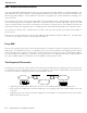
Introduction ARP—Address Resolution Protocol A protocol called ARP (Address Resolution Protocol) is used to determine the MAC address of a particular IP address. The MAC (Medium Access Control) address is unique predefined number for each device on the LAN. The manufacturer of the device assigns MAC addresses. The IP address for each device is assigned by the network administrator according to the network structure.
Introduction • Local router will receive the data frame and strip off the MAC portion. The resulting IP frame will be examined to determine the destination IP address. • Local router will look in its routing table to find the IP address of the router to send the IP frame to next. The local router will see that the destination router is the next router. • Local router will look in its ARP cache to find the MAC address of the destination router as determined by the IP address in the routing table.
Introduction IP Header Details Every IP header has common fields of information. The layout of the information is always the same. Refer to the following diagram for a representation of the IP header. Figure 1 - 2 IP Header Protocol The protocol section is used to indicate the protocol being used by the transport layer. This could be TCP, UDP, or something else. Time to live The time to live section is used to prevent a frame from traversing the network forever.
Introduction Options There are various options that may be set for any IP frame. Source Routing Source routing is used to predetermine the path that the IP frame must travel through the network. There are two types of source routing: strict source routing and loose source routing. Strict source routing will contain a list of IP addresses of routers that must be used when the IP frame is sent through the network. Strict source routing is used mainly to provide some type of data security.
Introduction Ping The “ping” message is actually a query status message that may be sent to devices on the LAN to determine their operation status. The LAN device will reply with a message if it is active. Time and Mask server Two other ICMP messages are used to query the time and/or subnet mask from a particular LAN device. A message is sent to a LAN device asking for the time or mask, and the device replies appropriately. 1.
Introduction RIP—Routing Information Protocol The most important function of the IP protocol is routing. IP routers constantly exchange information keeping their routing tables up to date. A method of communication is required to ensure compatibility between all IP routers in the network. RIP is the portion of the IP protocol that is used for router communication. Route Tables Each router will maintain a table of network addresses and the appropriate action to take with an IP frame it receives.
Introduction IPX Routing and The IOLINK-PRO & 520 Routers The IOLINK router may be used to route between IPX networks. Novell Netware uses a suite of protocols for LAN communications. The Novell protocols include IPX, SPX, RIP, SAP, plus others, and operate at layers 3 and above. These protocols, their relationship with each other, and the general operation of a Novell network are discussed in this section. The Netware Network Operating System implements the concept of “Client-Server” computing.
Introduction Node Addresses The Node Number identifies the individual stations in a Network. In IPX devices, this address is assigned automatically and is identical to the MAC address. This means that the Node Number is self-configuring, and will be unique within the Network because the MAC address that was copied is (supposed to be) unique. The use of the MAC address as the Node Number allows IPX stations to be self-configuring.
Introduction Establishing an IPX Connection The Netware model is Client/Server, where Clients initiate calls to Servers for various purposes. The Clients are made aware of the presence of Servers by listening for Service Advertisement Protocol (SAP) broadcasts. Servers send SAP broadcasts regularly to identify themselves, including their address and what type of service they offer (File Server, Print Server, Fax Server, etc.). Services also are referred to by their name.
Introduction SAP Requests Sometimes Clients will need to find out if a specific Server is available. This may occur immediately after a Client is brought up, and before it has received any SAP broadcasts. The Client (or a new Server) sends out a SAP Request broadcast asking for a specific Server. That Server, or a router with the best route to that Server, will respond to the Client (Server) making the request. Server Types There are many different types of Servers.
Introduction RIP/X Requests A Client may also request a route to a given network or server. To do so, the Client generates a Route Request broadcast that the routers hear, and routers that know of the route requested will respond to the originating station. In this way a new Client may find routes without waiting for the routers’ broadcast, that could be up to 30 seconds away (if it just missed one). A new router on a network will also broadcast a general Route Request to fill its route tables quickly.
Introduction The Initial Bridging Process Each time a IOLINK router is powered up, it will perform extensive hardware and software tests to ensure the integrity of the unit and its attached LAN and Link interfaces. Upon successful completion of the power-up diagnostics, the IOLINK router will follow rules to “learn” several aspects of your LAN environment. These rules define what actions are taken under particular situations.
Introduction Forwarding Unknown Destination Addresses When a frame is received from a LAN segment with an unknown destination address (an address that does not yet exist in the filter table), the bridge will forward the frame to the other segment, logging the address, and marking the location as “unknown”. Unknown Location Update When the receiving station transmits a frame in the opposite direction, the bridge will now see the previously unknown destination address in the source address field.
Introduction Aging Exception “Permanent” address entries are an exception to the aging rule. A permanent address is one that is not subject to the aging timer and will remain in the filter table for an indefinite period of time. A table is reserved for permanent address entries, separate from the table that is used for those non-permanent entries that are subject to aging. These tables may be displayed and modified with the bridge/router options discussed in this manual.
Introduction IOLINK Router Feature Definitions Telnet A Telnet LAN station or another IOLINK router has the ability to connect to the Operator Interface of any IOLINK router supporting the Telnet feature. With the Telnet feature, all IOLINK routers on a network may be managed from a single point. Once a connection is established, all of the menus of the other bridge/router are now available on the bridge/router that initiated the connection.
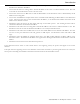
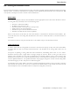
Introduction 7 6 5 4 Compression Ratio 3 2 1 0 Pre-compressed Binary Spreadsheet C Source ASCII Post Script Database Graphic File Type Figure 1 - 5 Typical Compression Ratios by File Type Data compression will give a 56/64 Kbps link an effective throughput range from 112/128 Kbps when transferring binary files, to 364/384 Kbps when transferring graphic files.
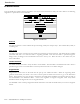
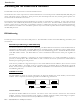
Introduction WAN Topologies The IOLINK router may be connected to other IOLINK routers in two configurations: Multipoint or Point-to-Point. The WAN routing method used is set in the WAN Set-Up Menu under the Link Operation option. Point-to-Point In a Point-to-Point configuration, two IOLINK routers are connected together with one or two WAN links. Each link may be set to an always active (unconditional) state or a backup/recovery (conditional) state.
Introduction To set up a Bandwidth on Demand installation, you would first connect the second link of the IOLINK router to a public circuit-switched network using the appropriate interface device. You would use high-speed modems with telephone lines, terminal adapters with an ISDN network, or digital modems with switched digital services. This second link would now be placed in a stand-by mode by setting Conditional operation option in the Secondary Activation Menu to Enabled.
Introduction Multipoint A simple Multipoint configuration would consist of a head office and two remote offices. Cost comparisons might reveal that it is less expensive to use a dial-up line during business hours only instead of a permanent leased line. One IOLINK router will be installed at each office (for a total of three units). Each IOLINK router at the remote office locations will connect to a separate link on the IOLINK router at the head office.
Section 2 — ISDN Connection Management IOLINK PRO & 520 ISDN Connection Management In the world of ISDN the ability to decrease connection time is a financial bonus in the LAN interconnecting marketplace. If ISDN connections can be controlled so that a minimum amount of cost is incurred while full LAN interconnecting functionality is retained, the overall cost for WAN communications can be minimized.
ISDN Connection Management Auto-Call (Time-of-Day Connections) An Auto-Call connection is an ISDN connection that is established each time the IOLINK router attempts to start the link. This starting of the links occurs each time an IOLINK router powers up or when the link goes through a restart or at the times specified by the Time-of-Day Activation Schedule. An Auto-Call connection would be used for a static WAN configuration that needs to be maintained at all specified times between sites.
ISDN Connection Management Address Connect An Address Connect connection is an ISDN connection that is established to a specific destination IOLINK router dependent upon the destination network address contained within traffic received from the local LAN. When a device on the local LAN wishes to establish a session with a device on a remote LAN, the local device will send a frame with a destination address of the remote device.
ISDN Connection Management Combination A combination of the Address Connect and Auto-Call options may be configured when a semi-permanent connection is required to one remote site and a dynamic connection is required to multiple sites. A dynamic connection indicates that the remote site for the second ISDN call will change depending upon what destination IP address is required for the connection.
ISDN Connection Management Protocol Awareness For Connection Management to be effective, each of the IOLINK routers must be aware of the protocols used within the data being transferred over the ISDN calls between them. IP and IPX Client-Server sessions are established between devices located on the LANs that are routed by the IOLINK Router.
ISDN Connection Management When the IOLINK router receives a keepalive packet from the LAN for one of the sessions, the IOLINK router will not activate the ISDN call and will not pass the keepalive packet to the remote LAN. The IOLINK router will generate a response to the keepalive packet and send it to the originator of the packet. In this way, the IOLINK router will keep the ISDN call suspended and will also keep the local side of the session active.
ISDN Connection Management IP Specifics IP Address Connect As stated previously, an IP Address Connect connection is an ISDN connection that is established to a specific destination IOLINK router dependent upon the destination IP address contained within IP traffic received from the local LAN. This means that the IOLINK router continuously monitors IP traffic from the local LAN, as all IP routers do, and makes ISDN connections to partner IOLINK routers when IP traffic needs to be sent to remote LANs.
ISDN Connection Management IPX Specifics RIP/IPX and SAP/IPX IOLINK ISDN routers incorporate a 3 second settling time for IPX RIP and SAP updates. This means that an IOLINK will wait for three seconds after an initial change in the network is reported before transmitting that change on to the remaining IOLINK routers connected on the Wide Area Network.
Section 3 — Link Interfaces Reference Pinout Information Each link interface available is described with detailed information on pin designation. Standard interface cables will provide correct connections to modems, datasets, or DSU/CSUs. When connecting two bridge/routers back-to-back without modems, a null-modem cable is required to crossover the pins on the links. Crossing over the pins allows two bridge/routers both configured as DTE interfaces to be connected together.
Link Interfaces Reference The IOLINK-PRO and 520 routers are currently produced with LXT CSU/DSU interface modules which have their link speed configured in software (please see the PPP menus manual for configuration options); however, the earlier model ATL CSU/DSU module is still compatible with the IOLINK router and may be used with it.
Link Interfaces Reference Console Pinouts The connector shown here and pinouts described here correspond to the connector labeled “Console” on the back of the IOLINK-PRO & 520. 1 13 25 14 DB25 Female DCE Contact Number 1 2 3 5 6 7 8 20 22 CCITT Circuit Number 101 103 104 106 107 102 109 108.
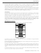
Link Interfaces Reference CSU/DSU Module: The CSU/DSU interface module uses a standard RJ45 service connector, pinout specification RJ48S. CSU/DSU Figure 3 - 5 Rear View of the CSU-DSU Connector The LXT411 CSU/DSU link connection is set to operate at 64 Kbps by default. The link may be set to 56 Kbps via the software menus if required.
Link Interfaces Reference V.24 & RS232C Link Pinouts The connector shown here and pinouts described here correspond to the connector labeled “RS232/ V.24” on the back of the IOLINK-PRO & 520. 1 13 25 14 DB25 Female DTE Contact Number 1 2 3 4 5 6 7 8 9 10 11 12 13 14 15 16 17 18 19 20 21 22 23 24 25 CCITT Circuit Number 101 103 104 105 Circuit AA BA BB CA 107 102 109 CC AB CF 114 DB 115 141 DD 108.
Link Interfaces Reference V.11 & X.21 Link Pinouts The connector shown here and pinouts described here correspond to the connector labeled “V.11/X.21” on the back of the IOLINK-PRO & 520. 8 1 15 9 DB15 Female DTE Contact Number 1 2 3 4 5 6 7 8 9 10 11 12 13 14 15 X.
Link Interfaces Reference RS442 & RS530 Link Pinouts The connector shown here and pinouts described here correspond to the connector labeled “RS530” on the back of the IOLINK-PRO & 520.
Link Interfaces Reference V.35 Link Pinouts 1 13 25 14 DB25 Female DTE DB25 Contact Number 1 2 3 4 5 6 7 8 9 10 11 12 13 14 15 16 17 18 19 20 21 22 23 24 25 M.34 Contact Number A CCITT Circuit Number C 105 E B F P S R T 107 102 109 103 103 104 104 V 115 X 115 U W H J Y 113 113 108.
Link Interfaces Reference RS232 Null-Modem Cable Configuration DB25 MALE DB25 MALE 1 Shield 2 Transmitted Data 3 Received Data 4 Request To Send 6 Data Set Ready Shield Received Data 3 Transmitted Data Signal Ground 8 Received Line Signal Detector (CD) 2 Data Set Ready 6 Request To Send 20 DTE Ready 7 1 4 Received Line Signal Detector (CD) 8 Signal Ground 7 DTE Ready 20 15 Transmit Timing DCE Source Receiver Timing DCE Source 17 17 Receiver Timing DCE Source Transmit Timing DCE
Link Interfaces Reference V.
Link Interfaces Reference RS530 Null-Modem Cable Configuration DB25 MALE 1 Shield 2 Transmitted Data (A) 14 Transmitted Data (B) 3 3 2 Transmitted Data (B) 14 DCE Ready (A) Request To Send (A) 6 DCE Ready (B) 22 Clear To Send (A) Clear To Send (A) 5 Clear To Send (B) 13 13 Clear To Send (B) 6 Received Data (A) Transmitted Data (A) Received Data (A) 19 Request To Send (B) 5 1 Received Data (B) 16 16 Received Data (B) 4 DB25 MALE Shield DCE Ready (A) Request To Send (A) 22 DCE Rea
Link Interfaces Reference RS530 To RS449 Conversion Cable DB25 MALE DB37 MALE/FEMALE 2 Transmitted Data (A) 4 14 Transmitted Data (B) 22 3 Received Data (A) 6 16 Received Data (B) 24 8 Received Line Signal Detector (A) 13 10 Received Line Signal Detector (B) 31 6 Data Set Ready (A) 11 22 Data Set Ready (B) 29 4 Request to Send (A) 7 19 Request to Send (B) 25 5 Clear to Send (A) 9 13 Clear to Send (B) 27 20 Data Terminal Ready (A) 12 23 Data Terminal Ready (B) 30
Link Interfaces Reference V.11/X.21 Null-Modem Cable Configuration Figure 3 – 15 V.11/X.21 Null-Modem Cable The connecting cable must be a shielded cable. Circuits which are paired (contain an (A) and (B) reference) should be connected to twisted pairs within the connecting cable. This cable is needed when it is necessary to connect two units back-to-back and a set of modems is not available.
Link Interfaces Reference WAN Link Control-Signal Operation CTS flow control is not supported. It is assumed that Dial In/Dial Out modes of dial-up operation will be configured externally to the bridge/router, i.e. on the attached modem, by setting Originate Only/Answer Only modes. A dataset or DSU/CSU can be used for a leased-line operation. 1) When a call is made to the bridge/router, RI will be asserted by the modem.
Appendix A - Event Logs The IOLINK router generates event logs for various functions performed by the bridge/router. All of the event logs are stored in the internal event log file, which is accessible through the Network Events menu. Certain event logs are classified as alarms because they are deemed to be of higher urgency. Alarm logs are indicated by an asterisk (“* ”) at the start of the alarm text and are printed on the ALARM line on the menu system as well as being stored in the event log.
Event Logs Completed BACP negotiation with Generated when the Bandwidth Allocation Control Protocol negotiation has been completed with the remote site device associated with the stated remote site profile. Once BACP negotiations are complete, the two routers will negotiate when required to bring up the second link.
Event Logs DHCP services – release. released. Generated when IP address displayed is released from its assignment to a device and put back in the IP pool for reassignment. Error executing: XXXXXX Generated when an error is detected loading back a configuration. The invalid command is specified. Incorrect password from Generated when an incorrect password is given for a Telnet connection. The connecting bridge/router’s name or IP address is specified.
Event Logs LCP X establishing Generated when the Link Control Protocol of a PPP link or remote site is establishing between this device and the remote site PPP device. LCP X no reply to Y Echo-Requests Generated just prior to a link going down. The link or remote site has gone down due to no replies to the echo request messages sent.
Event Logs Link X CSU/DSU: Loopback Started Generated when the CSU/DSU link module starts a new loopback test. Link X - CSU/DSU out of service Generated when the CSU/DSU is in communication with the local telco, but is not connected to the remote partner CSU/DSU. Link X CSU/DSU: No Signal Generated when the CSU/DSU link module cannot establish communications with the local telco. Link X CSU/DSU: Reset Generated when the IOLINK router has initiated a reset of the CSU/DSU link module.
Event Logs LMI discarding STATUS on link X – Enquiries not started Generated when the bridge/router discards a Status message received from the frame relay network on a link that the bridge/router has not yet started the Local Management Interface. No NCP's open, tearing link down Generated when a PPP link does not have a Network Control Protocol operating. This may be due to BCP, IPCP, and IPXCP being disabled, or the NCP connection was not negotiated to completion.
Event Logs Starting BACP negotiation with Generated when the Bandwidth Allocation Control Protocol negotiation has been initiated with the remote site device associated with the stated remote site profile. Starting BCP negotiation with Generated when the Bridging Control Protocol negotiation has been initiated with the remote site device associated with the stated remote site profile.
Event Logs TFTP: getting filename A LAN device with IP address displayed is getting a file (filename) from the bridge/router. TFTP: putting filename A LAN device with IP address displayed is putting a file (filename) onto the bridge/router. A.
Event Logs Alarm Logs: * Auto-learning of LMI type on link X unsuccessful Generated when the LMI type on a link is not successfully auto-learned. * Backup Battery is bad The backup battery power for memory backup has dropped below operating level, replace the batteries (see Installation and Applications Manual, Appendix D. * Bad internal block checksum detected Generated when power up diagnostics finds a fault in the internal block of the EEPROM.
Event Logs * Closing remote site X (no NCPs open) Generated when no Network Control Protocols operating. * Closing remote site X (nonexistant) Generated when remote site being deleted by the operator. * Closing remote site X (not enabled) Generated when remote site autocall being disabled by the operator. * Closing remote site X (PVC change) Generated due to the enabling or disabling of PPP encapsulation over frame relay.
Event Logs * Download aborted – Incomplete file Generated when a TFTP download is abortet before the file transfer is complete * Download aborted – Invalid FCS Generated when there is a checksum failure after a file download. * Download aborted – Incompatible boot code Generated when the operating code file downloaded is incopatible with the boot code in this device. The updated boot code software must be loaded before the operating code can be updated.
Event Logs * FTP server added to firewall The IP address of the FTP server added to the table of services available through the firewall. * FTP server removed from firewall The IP address of the FTP server removed from the table of services available through the firewall. * Gopher server added to firewall The IP address of the Gopher server added to the table of services available through the firewall.
Event Logs * Link X Connected Generated when and end-to-end ISDN call has been established. * Link X connection rejected Generated when Link X connection is being terminated as it could not be attached to a remote site. This may be due to usage limits or suspension resumptions. * Link X - CSU/DSU not responding, Power Cycle Device. Generated when the IOLINK router cannot establish communications with the CSU/DSU link module.
Event Logs Code 033 034 035 036 037 038 039 040 041 042 043 044 045 046 047 049 050 051 052 053 054 055 056 057 058 063 065 066 067 068 069 070 079 081 082 083 084 085 086 087 088 089 090 091 092 093 095 096 097 098 099 100 101 102 111 127 Description Circuit out of order No circuit/channel available Destination unattainable Out of order Degraded service Network out of order Transit delay range cannot be achieved Throughput range cannot be achieved Temporary failure Switching equipment congestion Access in
Event Logs * Link X, DLCI Y attached to remote site Generated for frame relay applications when a connection has been made for the DLCI associated with the remote site alias. * Link X down Generated when a WAN link goes down. * Link X down to Generated when a PPP ISDN call to a remote site is dropped. * Link X down to Generated when a WAN link connection to the specified remote site goes down.
Event Logs * Link X up at Y baud Generated when frame relay link is established. * Link X up to Generated when a WAN link connection to the specified remote site comes up. * Local DNS server added to firewall The IP address of the Local DNS server added to the table of services available through the firewall. * Local DNS server removed from firewall The IP address of the Local DNS server removed from the table of services available through the firewall.
Event Logs * No ISDN line available for remote site All ISDN lines are currently in use; none are available for the new connection requested. May be generated when CMCP is enabled and more ISDN calls are attempted than there are available ISDN lines. * No ISDN resource available for remote site All ISDN lines are currently in use; none are available for the new connection requested.
Event Logs * Remote site frame relay closing Generated when frame relay is diabled on the link to the specified remote site. * Remote site resumed Generated when the connection to the specified remote site has been resumed. * Remote Site still closing Generated when a connection is attempted to a remote site whose link is still in the process of being disconnected.
Event Logs * TFTP: Abort. Error (#) received Aborted a TFTP session because of the reception of a TFTP error message from the connected device. The errors are: 0 - not defined, 1 - file not found, 2 - access violation, 3 - disk full or allocation exceeded, 4 - illegal TFTP operation, 5 - unknown transfer ID, 6 - file already exists, 7 - no such user. * Unable to route!! UDP failure Generated when the device tried to open an already open UDP channel, causing IP routing to fail.
Event Logs PPP Security Logs: CHAP authentication failure so terminate link. Generated when the CHAP authentication sent by this router in response to a request from a remote site is rejected. CHAP failed for Generated when the remote site router failed a CHAP authentication request from this IOLINK router. The remote site name is displayed if known.
Appendix B - Programmable Filtering Programmable filtering gives the network manager the ability to control under what conditions Ethernet frames are forwarded across bridge or bridge/router ports. There are many reasons why this might need to be accomplished, some of which are security, protocol discrimination, bandwidth conservation, and general restrictions. To reach a specific filtering goal, there is usually more than one possible filter expression that may be used.
Programmable Filtering Security—“Filter if Destination” Filter if Destination is a function that allows you to filter an Ethernet frame based on the destination of its address. If the destination address equals the address that the Filter if Destination function has been applied to, the frame is filtered.
Programmable Filtering Security—“Filter if Source” Filter if Source is a function that allows you to filter an Ethernet frame if the source address of the frame equals the address that the Filter if Source function has been applied to. Example: Assume that a Personal Computer is located on segment 1 on the local bridge/router. This station is a community station that various departments may use for general processing.
Programmable Filtering 8 The bridge/router will prompt you for the LAN that the station is located on; enter the name of the partner bridge/router LAN (LAN345678, for example). Note that the Status of the address is marked as [present], the location is updated to LAN345678 and the Permanent entry is [enabled]. 9 Enter a 3 to [enable] the “Filter if Source” parameter. The edit screen will be updated to show the new information.
Programmable Filtering 4 From the MAC ADDRESS FILTERS MENU, make sure that the Filter Operation is currently set to “negative.” This will cause the MAC Address Filters specified to be used for forwarding frames with the specified MAC addresses. 5 From the MAC ADDRESS FILTERS MENU, enter a 1. This will place you at the first EDIT MAC ADDRESS FILTER MENU screen. At the prompt enter the MAC address for which you want to specify the filter.
Programmable Filtering 2 From the CONFIGURATION MENU, enter an 8. This will place you at the FILTER SET-UP MENU, where access to the individual filtering menus is obtained. 3 From the FILTER SET-UP MENU, enter a 1. This will place you at the MAC ADDRESS FILTERS MENU, where access to the MAC Address filters is obtained. 4 From the MAC ADDRESS FILTERS MENU, make sure that the Filter Operation is currently set to “negative.
Programmable Filtering Pattern Filter Operators The following operators are used in creating Pattern filters and will be discussed further in the following pages. For additional information refer to the octet locations diagrams at the back of this manual. Each octet location may contain a HEX value. - offset Used in pattern filters to determine the starting position to start the pattern checking. Example: | OR 12-80 Used in combination filters when one or the other conditions must be met.
Programmable Filtering The Bridge Filter Patterns menu is located under the FILTER SET-UP MENU. Within the Bridge Filter Patterns Menu there exists a Help function that can be used as a reference during Bridge Filter Pattern creation. This Help function includes all of the logical operators that may be applied to the mask expression. Protocol Type Field Within an Ethernet frame, a protocol field exists at octet 12 and 13.
Programmable Filtering Transport Control Protocol / Internet Protocol (TCP/IP) The previous example showed how to filter all Ethernet frames that contained an IP protocol packet. However, IP is used as the Network-layer protocol for more than 40 different Transport-layer protocols, TCP being only one of them. Therefore, with the mask that was used as noted in the previous IP example, all Transport layer protocols that used IP would also be filtered. This may not be desirable in all cases.
Programmable Filtering DEC DEC uses protocol types 6000 to 600F, and although some are undefined, a simple filter mask can be created to filter all DEC traffic. Filter all DEC The mask to filter all DEC traffic would be: 12-600X The X is a variable representing the last four bits (a nibble) of the type. This will effectively filter all Ethernet frames that contain a protocol type of 6000 through to 600F. All 16 possible combinations are covered.
Programmable Filtering General Restrictions Bridge Filter Masks may be created to generally restrict access for various purposes. Some of these purposes may be to filter specific combinations of information. This section will generally depict masks that may be created to control traffic across the bridged LAN network. Internet Addresses Within the Internet Protocol, there exist two address fields that are designated the Source and Destination Internet Addresses.
Programmable Filtering Mask Combinations Mask combinations may be required to ensure that a frame is sufficiently qualified before the decision to filter is made. The qualification a frame must go through before a filter decision is made depends on the reason for the filter. Nonetheless, a few examples below have been provided that should aid in the creation of a mask that may require that extra little bit of qualification.
Programmable Filtering IP Router Pattern Filtering Pattern filtering may be used on any portion of the IP frame. IP pattern filtering behaves the same as bridge pattern filtering, except the start of the IP frame is offset 0, because the IP router function of the bridge/router handles only the IP frame itself. IP pattern filtering may use any combination of filtering operators as described in the bridge pattern filters.
Appendix C - Frame Formats This appendix provides octet locations for the various portions of three of the common Ethernet frames. When creating pattern filters these diagrams will assist in the correct definition of the patterns. The offset numbers are indicated by the numbers above the frame representations. Note the differences in the TCP/IP and Novell frames when bridging and when routing.
Frame Formats ETHERNET TYPE CODES Type Code Description 0800 DOD IP 0801 X.75 Internet 0804 Chaosnet 0805 X.
Frame Formats Octet Locations on an IPX Routed Novell Netware Frame Octet Locations on a Bridged XNS Frame IOLINK-PRO & 520 Reference Manual — C.