Perle P840 Bridge/Router with VPN Reference Manual All Software Versions Part number 5500063-12 © copyright 2002 by Perle Systems Ltd.
1 Introduction The P840 Router The P840 router provides IP routing combined with a protocol transparent bridge. This bridge/router combination is often the best solution to linking remotely located LANs where most of the traffic is IP with smaller amounts of traffic from other protocols such as NetBIOS or DEC LAT. The P840 router supports the widely implemented Routing Information Protocol, otherwise known as RIP. RIP support allows the P840 router to interoperate with other vendors’ routers.
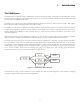
Introduction IP Routing and the P840 Router The P840 router may be used to route between subnets within the same network or between different networks. Network broadcasts sent within a subnet-routed environment will not be forwarded to the other subnets in the network. The procedure for establishing an IP connection through an IP router is explained on the next few pages.
Introduction The Complete IP Connection The following are the steps that a frame of data will take when being transmitted from an originating station on an IP network to a destination station on a different IP network. In this example, the two networks are separated by a third network. • Originating station will send an ARP request if it does not have the MAC address of the destination station.
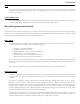
Introduction IP Header Details Every IP header has common fields of information. The layout of the information is always the same. Refer to the following diagram for a representation of the IP header. Figure 1 —2 IP Header Protocol The protocol section is used to indicate the protocol being used by the transport layer. This could be TCP, UDP, or something else. Time to live The time to live section is used to prevent a frame from traversing the network forever.
Introduction Source Routing Source routing is used to predetermine the path that the IP frame must travel through the network. There are two types of source routing: strict source routing and loose source routing. Strict source routing will contain a list of IP addresses of routers that must be used when the IP frame is sent through the network. Strict source routing is used mainly to provide some type of data security.
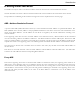
Introduction Ping The “ping” message is actually a query status message that may be sent to devices on the LAN to query their operation status. The ping message is basically a message asking “Are you alive?” The LAN device will reply with a message if it is active. Time and Mask server Two other ICMP messages are used to query the time and/or subnet mask from a particular LAN device. A message is sent to a LAN device asking for the time or mask, and the device replies appropriately.
Introduction Bridging and the P840 Router The bridge portion of the P840 router is an Ethernet Media Access Control (MAC) level bridge providing an efficient means of interconnecting IEEE 802.3 Local Area Networks supporting a choice of standard Ethernet (10Base5), Thin Ethernet (10Base2) and Twisted Pair (10BaseT) interfaces.
Introduction Forwarding Once the initial learning process is complete, the bridge/router enters a forwarding mode and examines frames that may need to be forwarded. The learning process does not stop at this time, however: The bridge/router will continue learning new stations as they become active on a LAN segment.
Introduction Address Purging To achieve this routine housekeeping, the filter table contains the LAN addresses, along with their LAN port identifier, and a timer flag. Each time a particular address is looked up or added to the table, a timer flag is set for the “fresh” entry. When a time interval, defined by the Bridge/Router Manager expires, the address table is scanned and any “stale” entries that have not been used since the timer expired are removed.
Introduction P840 Router Feature Definitions Telnet A Telnet LAN station or another P840 router has the ability to connect to the Operator Interface of any P840 router supporting the Telnet feature. With the Telnet feature, all of your P840 routers may be managed from a single point. Once a connection is established all of the menus of the other bridge/router are now available on the bridge/router that initiated the connection.
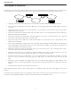
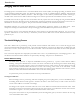
Introduction 7 6 5 4 Compression Ratio 3 2 1 0 Pre-compressed Binary Spreadsheet C Source ASCII Post Script Database Graphic File Type Figure 1 —3 Typical Compression Ratios by File Type Data compression will give a 56/64 Kbps link an effective throughput range from 112/128 Kbps when transferring binary files, to 364/384 Kbps when transferring graphic files.
Introduction WAN Topologies The P840 router may be connected to other P840 routers in two configurations: Multipoint or PPP Multilink. The WAN routing method used is set in the Remote Site profile defined in the Remote Site Set-Up Menu. Multilink In a Multilink configuration, two P840 routers are connected together with one or two WAN links. Each link may be set to an always active (unconditional) state or a backup/recovery (conditional) state.
Introduction To set up a Bandwidth on Demand installation, you must choose the throughput level that will be required for activating the stand-by link. The throughput level is measured in percentage of use of the primary link. This percentage level is defined by the Up Threshold parameter in the Secondary Activation Menu and may be set to any value from 50% to 100%. A timer must be defined to determine the length of time to wait before bringing up the stand-by link.
2 ISDN Connection Management P840 ISDN Connection Management In the world of ISDN the ability to decrease connection time is a financial bonus in the LAN interconnecting marketplace. If ISDN connections can be controlled so that a minimum amount of cost is incurred while full LAN interconnecting functionality is retained, the overall cost for WAN communications can be minimized.
ISDN Connection Management Auto-Call (Time-of-Day Connections) An Auto-Call connection is an ISDN connection that is established each time the P840 attempts to start the link. This starting of the links occurs each time a P840 powers up or when the link goes through a restart or at the times specified by the Time-of-Day Activation Schedule. An Auto-Call connection would be used for a static WAN configuration that needs to be maintained at all specified times between sites.
ISDN Connection Management Address Connect An Address Connect connection is an ISDN connection that is established to a specific destination P840 dependent upon the destination network address contained within traffic received from the local LAN. When a device on the local LAN wishes to establish a session with a device on a remote LAN, the local device will send a frame with a destination address of the remote device.
ISDN Connection Management Combination A combination of the Address Connect and Auto-Call options may be configured when a semi-permanent connection is required to one remote site and a dynamic connection is required to multiple sites. A dynamic connection indicates that the remote site for the second ISDN call will change depending upon what destination IP address is required for the connection.
ISDN Connection Management Protocol Awareness For Connection Management to be effective, each of the P840s must be aware of the protocols used within the data being transferred over the ISDN calls between them. IP Client-Server sessions are established between devices located on the LANs that are routed by the P840 router.
ISDN Connection Management P840 Session Participation (Spoofing) While an ISDN call is up and connected, all traffic within the sessions will be considered interesting and will be transferred to the partner P840 across the ISDN call. When the P840 determines that the ISDN call is to be suspended, the P840 will consider keepalive and routing information packets to now be non-interesting and will begin to generate and respond to keepalive and RIP packets.
ISDN Connection Management Termination Process When the P840 has determined that there are no sessions active on an ISDN call, the P840 will attempt to close the call. If the partner P840 still has sessions assigned to that call, the call will be maintained until each side has determined that there are no active sessions using the call. When the connection to the partner ISDN P840 is configured to use Auto-Call, the ISDN call will be suspended when there are no session in the table.
3 Interfaces Reference Pinout Information Console Connector The console connector on the P840 is a DCE interface on a RJ45 pinout. The supplied DB9 to RJ45 converter should be used to connect to the DB9 connector of a DTE terminal. This connection will then provide access to the built-in menu system. If the console interface is to be connected to a modem or other DCE device, a standard RS-232 crossover converter should be used. The following table illustrates the console pinouts.
4 Event Logs The P840 router generates event logs for various functions performed by the bridge/router. All of the event logs are stored in the internal event log file, which is accessible through the Network Events menu. Certain event logs are classified as alarms because they are deemed to be of higher urgency. Alarm logs are indicated by an asterisk (“*”) at the start of the alarm text and are printed on the ALARM line on the menu system as well as being stored in the event log.
Event Logs Completed BCP negotiation with Generated when the Bridging Control Protocol negotiation has been completed with the remote site device associated with the stated remote site profile. Once BCP negotiations are complete, IP routing may take place between the two routers. Completed CCP negotiation with Generated when the Compression Control Protocol negotiation has been completed with the remote site device associated with the stated remote site profile.
Event Logs ISDN link has had no traffic for longer than specified by the idle timer and has been disconnected. Incorrect password from Generated when an incorrect password is given for a Telnet connection. The connecting bridge/router’s name or IP address is specified. After three incorrect login attempts within ten minutes, an alarm is generated (see Security alarms: “Possible intruder”) and any further attempts from that IP address within the next ten minutes are rejected.
Event Logs LCP X authenticating peer with PAP Generated when this device is using PAP to authenticate the peer (remote) device. LCP X establishing Generated when the Link Control Protocol of a PPP link or remote site is establishing between this device and the remote site PPP device. LCP X no reply to Y Echo-Requests Generated just prior to a link going down. The link or remote site has gone down due to no replies to the echo request messages sent.
Event Logs Restoring boot DNLDSEG configuration Generated upon entering Network Load Mode to initialize specific configuration information required for retrieving new code image. Generated upon entering operational after a successful code burn into flash. Restoring boot EEPROM configuration Generated when restoring values in EEPROM configuration, this occurs when entering a load or operational mode. Running in System Load mode Generated when the bridge/router is starting in System Load (Boot) mode.
Event Logs Station address table has been filled Generated when the station address table is filled. This event is not regenerated until the table size drops below 3/4 full and then fills again. STP disabled Generated when STP is disabled. STP enabled Generated when STP is enabled. TFTP: stop putting filename to The bridge/router has sent the final data packet of a file (filename), but has timed out before receiving the final ACK.
Event Logs Alarm logs: * Bad internal block checksum detected Generated when power up diagnostics finds a fault in the internal block of the EEPROM. * Closing remote site X (call limit) Generated when the specified number of calls has been exceeded. * Closing remote site X (callback failure) Generated when the remote site interpreted the call sequence as a callback. However, a callback was not completed in the expected time frame.
Event Logs * Closing remote site X (usage limit) Generated due to reaching usage limit for this 24 hour period. * Config. erase failed Generated when, during a software update, the device configuration is not erased from the non-volatile memory within the time limit. Possible hardware fault. * Configuration saved Generated when the save configuration option has been activated.
Event Logs * DHCP server – out of addresses in IP pool Generated when the last address from the DHCP IP Address pool has been assigned to a device. * Download aborted – Incomplete file Generated when a TFTP download is aborted before the file transfer is complete * Download aborted – Invalid FCS Generated when there is a checksum failure after a file download. * Download aborted – Incompatible boot code Generated when the operating code file downloaded is incopatible with the boot code in this device.
Event Logs * FTP server added to firewall The IP address of the FTP server added to the table of services available through the firewall. * FTP server removed from firewall The IP address of the FTP server removed from the table of services available through the firewall. * ISDN BRI interface deactivated Generated when the ISDN link module has lost a physical connection to the NT-1. * ISDN BRI interface activated Generated when the ISDN link module has established a physical connection to the NT-1.
Event Logs * Link X Disconnect: Y Generated when the disconnect of an ISDN call is completed. This event is generated on both sides of the ISDN call. The cause will be one of the causes as specified in the CCITT Recommendation Q.931. Causes of “normal call clearing”, “User busy”, and “Number changed” are printed in words, all other are numeric.
Event Logs Code 055 056 057 058 063 065 066 067 068 069 070 079 081 082 083 084 085 086 087 088 089 090 091 092 093 095 096 097 098 099 100 101 102 111 127 Description Incoming calls barred within CUG Call waiting not subscribed Bearer capability not authorized Bearer capability not presently available Service or option not available, unspecified Bearer capability not implemented Channel type not implemented Transit network selection not implemented Message not implemented Requested facility not implement
Event Logs * Link X down Generated when a WAN link goes down. * Link X down to Generated when a PPP ISDN call to a remote site is dropped. * Link X down to Generated when a WAN link connection to the specified remote site goes down. * Link X Incoming Data Call [to/from] [callingDN/calledDN] Generated when an incoming data call is presented from ISDN and the caller directory number is not presented.
Event Logs * Local DNS server added to firewall The IP address of the Local DNS server added to the table of services available through the firewall. * Local DNS server removed from firewall The IP address of the Local DNS server removed from the table of services available through the firewall. * NAT UDP flooding – Possible security risk. Src is Generated when more than the allowed maximum number of UDP entries has been attempted. This feature is in place to prevent denial of service attacks.
Event Logs * Old download method! Load in \”*.all\” file Generated when an attempt is made to load a *.fcs or *.lda format program file into hardware which will only accept *.all format code. * Old format configuration, using default Generated when the saved configuration does not match the expected correct revision number. The old configuration formats will not be used.
Event Logs * Running in System Load mode Generated when entering System Load Mode in preparation for a download of code to be burned into flash. * SECURITY ALERT: SNMP community has write access enabled to “ALL” hosts The SNMP community displayed has had write access enabled to all hosts on the network; anyone may access any host to make changes. * Service added to firewall The IP address of the Service added to the table of services available through the firewall.
Event Logs * Unable to bind UDP Boot P server port Generated as a result of an internal device error. Try resetting the device. If this is unsuccessful, contact a service representative. * Unable to bind UDP DHCP server port Generated as a result of an internal device error. Try resetting the device. If this is unsuccessful, contact a service representative. * Unable to route!! UDP failure Generated when the device tried to open an already open UDP channel, causing IP routing to fail.
Event Logs PPP Security logs: CHAP authentication failure so terminate link. Generated when the CHAP authentication sent by this router in response to a request from a remote site is rejected. CHAP failed for Generated when the remote site router failed a CHAP authentication request from this P840. The remote site name is displayed if known.
5 Programmable Filtering Programmable filtering gives the network manager the ability to control under what conditions Ethernet frames are forwarded across bridge or bridge/router ports. There are many reasons why this might need to be accomplished, some of which are security, protocol discrimination, bandwidth conservation, and general restrictions. To reach a specific filtering goal, there is usually more than one possible filter expression that may be used.
Filtering Security—“Filter if Destination” Filter if Destination is a function that allows you to filter an Ethernet frame based on the destination of its address. If the destination address equals the address that the Filter if Destination function has been applied to, the frame is filtered.
Filtering Security—“Filter if Source” Filter if Source is a function that allows you to filter an Ethernet frame if the source address of the frame equals the address that the Filter if Source function has been applied to. Example: Assume that a Personal Computer is located on segment 1 on the local bridge/router. This station is a community station that various departments may use for general processing.
Filtering 8 The bridge/router will prompt you for the LAN that the station is located on; enter the name of the partner bridge/router LAN (LAN345678, for example). Note that the Status of the address is marked as [present], the location is updated to LAN345678 and the Permanent entry is [enabled]. 9 Enter a 3 to [enable] the “Filter if Source ” parameter. The edit screen will be updated to show the new information. At this point, the address is added to the permanent filter table of the local LAN.
Filtering 5 From the MAC ADDRESS FILTERS MENU, enter a 1. This will place you at the first EDIT MAC ADDRESS FILTER MENU screen. At the prompt enter the MAC address for which you want to specify the filter. 6 Enter the 12-digit Ethernet address of the host system in the following format: Return) 000001020304 (enter a The edit screen will fill in the information that the table knows about this address.
Filtering 4 From the MAC ADDRESS FILTERS MENU, make sure that the Filter Operation is currently set to “negative”. This will cause the MAC Address Filters specified to be used for forwarding frames with the specified MAC addresses. 5 At this menu, enter a 1. This will place you at the first EDIT MAC ADDRESS FILTER MENU screen. At the prompt enter the MAC address for which you want to specify the filter.
Filtering Pattern Filter Operators The following operators are used in creating Pattern filters and will be discussed further in the following pages. For additional information refer to the octet locations diagrams at the back of this manual. Each octet location may contain a HEX value. - offset Used in pattern filters to determine the starting position to start the pattern checking. Example: | OR 12-80 Used in combination filters when one or the other conditions must be met.
Filtering In Local Area Networks there may be many different Network and Transport layer protocols that coexist on the same physical media. TCP/IP, DECNET, and XNS are just a few of the common protocols in use today. Each of these protocols is encapsulated within an Ethernet frame, and therefore is transparent to the normal bridging function.
Filtering In this case, whenever a frame is received, the frame will be filtered if the protocol type is NOT equal to 0800 (IP). Only one filter pattern may be used that contains the NOT operator.
Filtering Transport Control Protocol / Internet Protocol (TCP/IP) The previous example showed how to filter all Ethernet frames that contained an IP protocol packet. However, IP is used as the Network-layer protocol for more than 40 different Transport-layer protocols, TCP being only one of them. Therefore, with the mask that was used as noted in the previous IP example, all Transport layer protocols that used IP would also be filtered. This may not be desirable in all cases.
Filtering DEC DEC uses protocol types 6000 to 600F, and although some are undefined, a simple filter mask can be created to filter all DEC traffic. Filter all DEC The mask to filter all DEC traffic would be: 12-600X The X is a variable representing the last four bits (a nibble) of the type. This will effectively filter all Ethernet frames that contain a protocol type of 6000 through to 600F. All 16 possible combinations are covered.
Filtering General Restrictions Bridge Filter Masks may be created to generally restrict access for various purposes. Some of these purposes may be to filter specific combinations of information. This section will generally depict masks that may be created to control traffic across the bridged LAN network. Internet Addresses Within the Internet Protocol, there exist two address fields that are designated the Source and Destination Internet Addresses.
Filtering Mask Combinations Mask combinations may be required to ensure that a frame is sufficiently qualified before the decision to filter is made. The qualification a frame must go through before a filter decision is made depends on the reason for the filter. Nonetheless, a few examples below have been provided that should aid in the creation of a mask that may require that extra little bit of qualification.
Filtering IP Router Pattern Filtering Pattern filtering may be used on any portion of the IP frame. IP pattern filtering behaves the same as bridge pattern filtering, except the start of the IP frame is offset 0, because the IP router function of the bridge/router handles only the IP frame itself. IP pattern filtering may use any combination of filtering operators as described in the bridge pattern filters.
6 Frame Formats This appendix provides octet locations for the various portions of three of the common Ethernet frames. When creating pattern filters these diagrams will assist in the correct definition of the patterns. The offset numbers are indicated by the numbers above the frame representations. Note the differences in the TCP/IP and Novell frames when bridging and when routing.
Frame Formats ETHERNET TYPE CODES Type Code Description 0800 DOD IP 0801 X.75 Internet 0804 Chaosnet 0805 X.
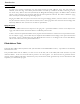
Frame Formats Octet Locations on an IP Routed TCP/IP Frame 57
Frame Formats Octet Locations on a Bridged XNS Frame 58