5500193-10 RPS Series Remote Power Switches Models Covered: RPS820 RPS830 RPS1620 RPS1630 User’s Guide
Warnings and Cautions: INSTALLATION INSTRUCTIONS SECURE RACKING If Secure Racked units are installed in a closed or multi-unit rack assembly, they may require further evaluation by Certification Agencies. The following items must be considered. 1. The ambient within the rack may be greater than room ambient. Installation should be such that the amount of air flow required for safe operation is not compromised. The maximum temperature for the equipment in this environment is 45°C.
RPS Series: Remote Power Switches - User's Guide FCC Part 15 Regulation This equipment has been tested and found to comply with the limits for a Class A digital device, pursuant to Part 15 of the FCC rules. These limits are designed to provide reasonable protection against harmful interference in a residential installation.
Table of Contents 1. Introduction . . . . . . . . . . . . . . . . . . . . . . . . . . . . . . . . . . . . . . . . . . . . . . . . . . . . . . . . . . 1-1 2. Unit Description . . . . . . . . . . . . . . . . . . . . . . . . . . . . . . . . . . . . . . . . . . . . . . . . . . . . . . . 2.1. RPS820 and RPS830 Front Panel . . . . . . . . . . . . . . . . . . . . . . . . . . . . . . . . . . . . . 2.2. RPS820 and RPS830 Back Panel. . . . . . . . . . . . . . . . . . . . . . . . . . . . . . . . . . . . . . 2.3.
RPS Series: Remote Power Switches - User's Guide 7. Saving and Restoring Configuration Parameters . . . . . . . . . . . . . . . . . . . . . . . . . . . . 7-1 7.1. Sending Parameters to a File . . . . . . . . . . . . . . . . . . . . . . . . . . . . . . . . . . . . . . . . . 7-1 7.2. Restoring Saved Parameters. . . . . . . . . . . . . . . . . . . . . . . . . . . . . . . . . . . . . . . . . . 7-2 8. Upgrading the RPS Firmware . . . . . . . . . . . . . . . . . . . . . . . . . . . . . . . . . . . . . . . . . .
1. Introduction Electronic equipment sometimes "locks-up" requiring a service call just to flip the power switch to perform a simple reboot. RPS Series Remote Power Switches give you the ability to perform this function remotely. If secure remote access is an issue, you can communicate through Perle’s IOLAN DS product line to securely manage the power status of your electronic equipment. To configure your environment for an RPS and a Perle IOLAN DS product, refer to the SCS/SDS/STS User’s Guide.
RPS Series: Remote Power Switches - User's Guide Four Different RPS Models This User’s Guide discusses four different RPS models. Throughout this User’s Guide, all four units are referred to as the "RPS". Aside from the hardware configuration, all other features function identically in both units except where noted. The table below summarizes the four RPS units covered in this manual: • RPS820: Horizontal mount. Eight (8) switched, 208 to 240 VAC, IEC-320-C13 outlets. 20 Amps maximum total load.
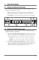
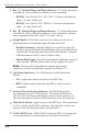
2. Unit Description 2.1. RPS820 and RPS830 Front Panel The front panels of both RPS820 and RPS830 models include two LED indicators which function as follows: • Power: Lights when power is applied to the unit. Note that this indicator does not show the On/Off status of the switched outlets. • System Ready: Flashes when the unit is ready to receive commands. 1 BUS A 9 8 BUS B A COM MAIN POWER B 2 A-1 A-2 A-3 A-4 B-5 3 B-6 B-7 4 B-8 DEF 5 ON 6 RDY 10BaseT ACT 7 Figure 2.
RPS Series: Remote Power Switches - User's Guide ➂ Bus "A" Switched Plugs and Plug Indicators: AC Outlets that can be switched On, Off or rebooted in response to user commands. • RPS820: Four 208-240 VAC, IEC-320-C13 Outlets with indicator lights. 10 Amps Total Load. • RPS830: Four 100-120 VAC, NEMA 5-15 Outlets with indicator lights. 15 Amps Total Load. ➃ Bus "B" Switched Plugs and Plug Indicators: AC Outlets that can be switched On, Off or rebooted in response to user commands.
Unit Description 2.3. RPS1620 and RPS1630 Hardware As shown in Figure 2.2, RPS1620 and RPS1630 units includes power outlets, LEDs and a manual control button. The items in Figure 2.2 are described on the following page. 1 PLUGS READY ACTIVITY 2 3 10BaseT 4 RS232 CONSOLE (DTE) 5 Remote Power Switch 6 PLUG 1 PLUG 2 PLUG 3 7 PLUG 14 PLUG 15 PLUG 16 8 PWR CKT A 9 PWR CKT B Figure 2.
RPS Series: Remote Power Switches - User's Guide As shown in Figure 2.2, RPS1620 and RPS1630 units include the following components: Manual Switch Button: A Manual Control Button for the unit’s switched plugs. To manually switch plugs "On" or "Off", press and hold the control button for approximately three seconds. If desired, the Manual Switch Button can also be disabled (Section 5.3.1.) Note: When the Manual Switch Button is used, Boot / Sequence Delay Times will be applied as described in Section 5.
Unit Description Power Circuit "A" Input Components: An AC inlet and circuit breaker, which supply power to plugs one through 8: Model RPS1620: • Power Inlet: Two (2) 208 to 240 VAC, IEC-320-C14 AC inlets. • Circuit Breaker: 10 Amps. Model RPS1630: • Power Inlets: Two (2) 100 to 120 VAC, IEC-320-C14 AC inlets. • Circuit Breaker: 15 Amps. Power Circuit "B" Input Components: An AC Inlet and circuit breaker, which supply power to plugs 9 through 16. Includes same components as Circuit "A".
RPS Series: Remote Power Switches - User's Guide 2-6
3. Quick Start Guide This Quick Start Guide describes a simplified installation procedure for the RPS820, RPS830, RPS1620 and RPS1630, which will allow you to communicate with the unit in order to demonstrate basic features and check for proper operation. In order to take full advantage of the complete range of features offered by this unit, it is recommended to complete the remainder of this User's Guide after performing the Quick Start Procedure. 3.1. Hardware Installation 3.1.1.
RPS Series: Remote Power Switches - User's Guide 3.1.2. Connect your PC to the RPS The RPS can either be controlled by a local PC Serial Port, controlled via external modem, or controlled via TCP/IP network. In order to switch plugs or select parameters, commands are issued to the RPS via the Network Port or Console/RS232 Port. Note that it is not necessary to connect to both the Network and RS232 Ports, and that the RS232 Port can be connected to either a local PC or External Modem.
Quick Start Guide To communicate with the RPS unit, proceed as follows: 1. Access Command Mode: This procedure differs slightly for the Web Browser Interface and Text Interface: a) Web Browser Interface: Start your JavaScript enabled Web Browser. Enter the RPS’s default IP address (192.168.168.168) in the address bar, then press [Enter]. A password prompt will be displayed. Since at this point, the username and password have not been defined, you can simply click OK without entering a username or password.
RPS Series: Remote Power Switches - User's Guide Figure 3.1: Plug Status Screen - Web Browser Interface (Model RPS830 Shown) Remote Power Switch v1.43s Site ID: (undefined) Plug | Name | Password | Status | Boot/Seq. Delay | Default | -----+------------------+-------------+--------+-----------------+---------+ 1 | (undefined) | (undefined) | ON | 0.5 Secs | ON | 2 | (undefined) | (undefined) | ON | 0.5 Secs | ON | 3 | (undefined) | (undefined) | ON | 0.5 Secs | ON | 4 | (undefined) | (undefined) | ON | 0.
Quick Start Guide 2. Test Switching Functions: You may wish to perform the following tests in order to make certain that the RPS is responding to commands. a) Reboot Outlet: If you are communicating with the unit via the Web Browser Interface, select the button in the "Boot" column for Plug 1, and then click on "Apply." If you are operating the unit via the Text interface, type /BOOT 1 and press [Enter].
RPS Series: Remote Power Switches - User's Guide 3-6
4. Installation This section provides further details regarding the connections that are made in the process of installing the RPS. 4.1. Power Supply Connection Before you connect the RPS to your power supply, it is recommended to install the Cable Keepers, which will secure the power supply cables to the RPS unit. To install the Cable Keepers, first, make certain that both power cables are disconnected from your power supply.
RPS Series: Remote Power Switches - User's Guide 4.2. Connection to Switched Outlets Connect the power cord from each device that you wish to control, to a Switched AC Outlet on the RPS unit. Note that when power is applied to the RPS in the default state, the Switched Outlets will all initially be switched "ON".
Installation 4.4. Connecting the Network Cable The Network Port is an RJ45 Ethernet jack, for connection to a TCP/IP network. Connect your 10Base-T cable to the Network Port. Note that the RPS includes a default IP address (192.168.168.168) and a default subnet mask (255.255.255.0.) When installing the RPS in a working network environment, it is recommended to define network parameters as described in Section 5.3.4. Note: The RPS features a 10Base-T Interface.
RPS Series: Remote Power Switches - User's Guide 4-4
5. Configuration 5.1. System Mode and User Mode In order to restrict access to sensitive command functions, the RPS features two operating modes; System Mode and User Mode. • System Mode: Allows access to all configuration menus, switching functions and status screens. The System Mode Status Screens show On/Off conditions for all switched outlets, and list all currently defined system parameters.
RPS Series: Remote Power Switches - User's Guide Figure 5.1: Plug Status Screen - Web Browser Interface (Model RPS830 Shown) 5.2. Communicating with the RPS In order to configure the unit or invoke command functions, you must first connect to the RPS and access the command mode. As discussed in Section 3, the RPS offers two separate command interfaces: the Web Browser Interface, and the Text Interface.
Configuration 5.2.1. Accessing the Web Browser Interface In order to issue commands via the Web Browser Interface, the RPS must be connected to a TCP/IP network, and your PC must be equipped with a JavaScript enabled web browser (such as Internet Explorer™ or Netscape™ Navigator.) 1. Start your JavaScript enabled Web Browser. 2. Key the RPS’s IP address (default = http://192.168.168.168) into the web browser’s address bar, and then press [Enter]. 3.
RPS Series: Remote Power Switches - User's Guide Remote Power Switch v1.43s Site ID: (undefined) Plug | Name | Password | Status | Boot/Seq. Delay | Default | -----+------------------+-------------+--------+-----------------+---------+ 1 | (undefined) | (undefined) | ON | 0.5 Secs | ON | 2 | (undefined) | (undefined) | ON | 0.5 Secs | ON | 3 | (undefined) | (undefined) | ON | 0.5 Secs | ON | 4 | (undefined) | (undefined) | ON | 0.5 Secs | ON | 5 | (undefined) | (undefined) | ON | 0.
Configuration To access command mode via the Text Interface, proceed as follows: 1. The RPS is transparent to parity and will accept 7 or 8 bit characters, but will always answer back at 8 bits, no parity. Make certain your communication program is set for the appropriate baud rate, bits, parity and Comm Port. a) Via Modem: Start your communications program. Dial the external modem connected to the RPS. Wait for the Connect message, then proceed to Step 2.
RPS Series: Remote Power Switches - User's Guide 5.3. Configuration Menus As described in the sections that follow, configuration parameters for the RPS can be selected via the Web Browser Interface or Text Interface. Although the Web Browser and Text Interface provide two separate means for selecting parameters, both interfaces allow access to essentially the same set of parameters, and parameters selected via one interface will also be applied to the other.
Configuration Figure 5.3: General Parameters Menu - Web Browser Interface GENERAL PARAMETERS: 1. 2. 3. 4. 5. 6. 7. 8. System Password: (undefined) User Name: (undefined) Site ID: (undefined) Command Echo: On Inactivity Timeout: 2 Mins Command Confirmation: On Automated Mode: Off Manual Switch Button: On A. Default Parameters Enter Selection, Press to Exit ... Figure 5.
RPS Series: Remote Power Switches - User's Guide The General Parameters Menu allows the following parameters to be defined. • System Password: The RPS will display a password prompt when you attempt to access command mode. When the System Password is entered at log on, the System Mode will be active, allowing access to both switching functions and configuration menus. (16 Characters, Default = undefined.
Configuration • Inactivity Timeout: Determines how long the RPS will wait for additional commands during periods of inactivity. When the Timeout Period elapses, the user will be disconnected from the RPS command mode. (Default = 2 Minutes.) • Command Confirmation: When enabled, the RPS will display a confirmation prompt before executing certain commands. When disabled, the prompt will be suppressed and commands will be executed immediately. (Default = On/Enabled.
RPS Series: Remote Power Switches - User's Guide Figure 5.5: Serial Parameters Menu - Web Browser Interface SERIAL PARAMETERS: 1. 2. 3. 4. 5. 6. Baud Rate: Data: Parity: Stop: Port Mode: Modem Init. Str: 9600 8 Bit None 1 Bit Console ATE0M0Q1&C1&D2S0=1 Enter selection, Press to return to previous menu ... Figure 5.6: Serial Parameters Menu - Text Interface 5.3.2.
Configuration As shown in Figure 5.5 and Figure 5.6, the Serial Parameters Menus allow you to define the following parameters: Note: When the baud rate, data bits, parity or stop bits settings are changed via the console port, newly selected parameters will not be applied until the user exits and then re-enters command mode. • Baud Rate: The Baud Rate for the serial Console Port. (Default = 9600 bps.) • Data: The Data bits setting for the serial Console Port. (Default = 8 Bits.
RPS Series: Remote Power Switches - User's Guide Figure 5.7: Plug Parameters Menu - Web Browser Interface PLUG #3 PARAMETERS: 1. 2. 3. 4. Plug Name: Password: Boot/Seq. Delay: Power Up Default: (undefined) (undefined) 0.5 Secs On Enter Selection, Press to Exit ... Figure 5.8: Plug Parameters Menu - Text Interface 5.3.3.
Configuration Note that when defining plug parameters via the Web Browser Interface, the desired plug is selected using the dropdown menu at the top of the page. When defining plug parameters via the Text Interface, the plug is selected using the /P n command (where n is the number or name of the desired plug.) The Plug Parameters Menu allows the following parameters to be defined: • Plug Name: Assigns a name to the plug. (Up to 32 Characters, Default = undefined.
RPS Series: Remote Power Switches - User's Guide 5.3.3.1. Plug Passwords and Co-Location Features The Plug Passwords, which are defined via the Plug Parameters Menu(s) allow you to determine which plugs an individual user will be permitted to control. When a plug password is entered while logging into command mode, the user will be able to issue switching and reboot commands for the corresponding plug, and every other plug that shares this same password.
Configuration 5.3.3.2. The Boot / Sequence Delay Period. The Boot / Sequence Delay value will be applied differently for Reboot operations as opposed to simple On/Off operations as described below: 1. Reboot Cycles: a) Single Plug: The Boot/Seq. Delay determines how long the plug will remain Off before it is switched back On again. b) Several Plugs: The Boot/Seq.
RPS Series: Remote Power Switches - User's Guide 5.3.4. Network Parameters Menus The Network Parameters Menus are used to select the IP Address and other network parameters. • Web Browser Interface: Click the "Setup" button to access the Setup Menus, and then click the "Network Parameters" button. The Web Parameters Menu will be displayed as shown in Figure 5.9. • Text Interface: Type /N and press [Enter]. The Network Parameters Menu will be displayed as shown in Figure 5.10.
Configuration Figure 5.9: Network Parameters - Web Browser Interface NETWORK PARAMETERS: 1. 2. 3. 4. 5. IP Address: Subnet Mask: Gateway Address: Send MSS: IP Security MAC Address: 207.212.30.80 255.255.255.0 207.212.30.1 536 00-09-9b-00-90-e0 Enter Selection, Press to Exit ... Figure 5.
RPS Series: Remote Power Switches - User's Guide IP SECURITY: 1. 2. 3. 4. 5. 6. 7. 8. 9. 10. Security Mask #1: Mask #1 Action: Security Mask #2: Mask #2 Action: Security Mask #3: Mask #3 Action: Security Mask #4: Mask #4 Action: Security Mask #5: Mask #5 Action: (undefined) Permit (undefined) Permit (undefined) Permit (undefined) Permit (undefined) Permit Enter selection, Press to return to previous menu ... Figure 5.11: IP Security Menu - Text Interface 5.3.4.1.
Configuration Example 1: Deny access to all hosts except 192.1.1.5: Security Mask #1: 255.255.255.255 Security Mask #2: 192.1.1.5 Mask #1 Action: Deny Mask #2 Action: Permit Since 255 is a wild card, Mask #1 blocks all IP Addresses. Mask #2 then specifically grants access to 192.1.1.5 only. Example 2: Allow access only by addresses that begin with 192. Security Mask #1: 255.255.255.255 Security Mask #2: 192.255.255.
RPS Series: Remote Power Switches - User's Guide Figure 5.12: Telnet Parameters Menu - Web Browser Interface TELNET PARAMETERS: 1. Service: On 2. Telnet Port #: 23 3. Multiple Telnet: Off Enter Selection, Press to Exit ... Figure 5.13: Telnet Parameters Menu - Text Interface 5.3.5. The Telnet Parameters Menus The Telnet Parameters Menus are used to enable/disable Telnet access to the RPS command mode and select the TCP port for Telnet connections.
Configuration The Telnet Parameters Menus allow the following parameters to be defined. Please note that all parameters listed here are available via both the Web Browser Interface and Text Interface. • Service: Enables/Disables Telnet communication with the RPS unit. When this item is set to the "Off" condition, user’s will not be able to contact the unit via Telnet. (Default = On.) • Port Number: Selects the TCP/IP port number that will be used for Telnet connections. (Default = 23.
RPS Series: Remote Power Switches - User's Guide Figure 5.14: Web Browser Parameters Menu - Web Browser Interface WEB SERVER: 1. Service: 2. Server Port #: On 80 Enter Selection, Press to Exit ... Figure 5.15: Web Browser Parameters Menu - Text Interface 5.3.6. Web Server Parameters Menus The Web Server Parameters Menus are used to configure the RPS’s internal web server, which allows the unit to be operated via the Web Browser Interface.
Configuration The Web Server Parameters Menu allows the following parameters to be defined. Please note that all parameters listed here are available via both the Web Browser Interface and Text Interface. • Service: Enables/Disables the RPS’s Web Server. Note that when the Web Server is disabled, you will not be able to communicate via the Web Browser Interface. (Default = On.) • Port Number: Sets the TCP/IP Port Number.
RPS Series: Remote Power Switches - User's Guide 5-24
6. Operation As discussed in Section 5, "Configuration", the RPS offers two separate command interfaces; the Web Browser Interface and the Text Interface. Note that Both interfaces offer essentially the same command options and features, and that parameters defined via the Web Interface will also apply when communicating via the Text Interface (and vice versa.) 6.1.
RPS Series: Remote Power Switches - User's Guide Figure 6.1: Plug Status Menu - Web Browser Interface (Model RPS830 Shown) 4. Switching Plugs Off: Click the "Off" button next to the desired plug(s), and then click "Apply." To switch all plugs Off, click the "Off" button in the "All Plugs" row, and then click "Apply." 5. Reboot Cycle: Click on the "Boot" button next to the desired plug(s), and then click "Apply." To reboot all plugs, click the "Boot" button in the "All Plugs" row and then click "Apply." 6.
Operation Remote Power Switch v1.43s Site ID: (undefined) Plug | Name | Password | Status | Boot/Seq. Delay | Default | -----+------------------+-------------+--------+-----------------+---------+ 1 | (undefined) | (undefined) | ON | 0.5 Secs | ON | 2 | (undefined) | (undefined) | ON | 0.5 Secs | ON | 3 | (undefined) | (undefined) | ON | 0.5 Secs | ON | 4 | (undefined) | (undefined) | ON | 0.5 Secs | ON | 5 | (undefined) | (undefined) | ON | 0.5 Secs | ON | 6 | (undefined) | (undefined) | ON | 0.
RPS Series: Remote Power Switches - User's Guide Remote Power Switch v1.
Operation To switch plugs On/Off, initiate a reboot cycle, or set plugs to their Power Up Default values, proceed as follows: 1. Switch Plug(s) On: Type /ON n and press [Enter]. Where "n" is the number or name of the desired plug. For example: /ON 1 or /ON ROUTER 2. Switch Plug(s) Off: Type /OFF n and press [Enter]. Where "n" is the number or name of the desired plug. Note that the "/OFF" command can also be entered as "/OF". For example: /OFF 2 or /OF ROUTER 3.
RPS Series: Remote Power Switches - User's Guide 6.2.3. Applying Commands to Several Plugs - Text Interface As described below, switching and reboot commands can be applied to only one Switched AC Outlet, or to an assortment of outlets. • • Notes: When switching or reboot operations are initiated, Boot/ Sequence Delay times will be applied as described in Section 5.3.3.2.
Operation 6.3. Logging Out of Command Mode When you have finished communicating with the RPS, it is important to always disconnect using either the "Log Out" button (Web Browser Interface) or /X command (Text Interface), rather than simply closing your browser window or communications program.
RPS Series: Remote Power Switches - User's Guide To enable the Automated Mode, access the General Parameters menu (see Section 5.3.1) and then set the "Automated Mode" option to the "On" state. When the Automated Mode is enabled, RPS functions will change as follows: 1. All Password Security Suppressed: When a user attempts to access the command mode, the password prompt will not be displayed at either the Console Port or Network Port.
7. Saving and Restoring Configuration Parameters After the RPS has been properly configured, parameters can be downloaded and saved as an ASCII text file on your local or remote PC. Later, if the configuration is accidentally altered, the file with the saved parameters can be uploaded to automatically reconfigure the unit without the need to manually assign each parameter. Saved parameters can also be uploaded to other RPS units.
RPS Series: Remote Power Switches - User's Guide 7.2. Restoring Saved Parameters This section describes the procedure for using ProComm to send saved parameters to the RPS. Note: Parameters that have been saved to an ASCII file can only be restored via the Text Interface. This procedure cannot be performed via the Web Browser Interface. 1. Start your communications program and access the RPS command mode via the Text Interface as described in Section 5.2.2. 2.
8. Upgrading the RPS Firmware When new, improved versions of the RPS firmware become available, the "Upgrade Firmware" function can be used to update the unit. Updates can be installed via the Console Port or Network Port. • Notes: The upgrade procedure can only be performed via the Text Interface. • All other network ports will be disabled during the firmware upgrade procedure. • When the upgrade procedure is complete, all parameters will be set to their default states.
RPS Series: Remote Power Switches - User's Guide 4. Set your communication program for ASCII Mode, then use the program’s "Send File" function to transfer the upgrade file to the RPS. Select ASCII format, then specify the filename and directory location where the firmware upgrade file resides. 5. If the upload is successful, the RPS will load the upgrade firmware into memory, and then reboot itself.
A. Interface Descriptions A.1. Console Port Interface Figure A.
RPS Series: Remote Power Switches - User's Guide B.
Appendices Physical / Environmental: Size: Models RPS820 and RPS830 (Horizontal Mount): • Width: 17.5” (44.5 cm) Standard Rack • Depth: 7.0” (17.8 cm) • Height: 1.75” (4.5 cm) 1 Rack U Models RPS1620 and RPS1630 (Vertical Mount): • Width: 1.75" (4.5 cm) • Depth: 3.00" (7.6 cm) • Length: 43.75" (111.1 cm) Weight: • Model RPS820: 8 lbs. (3.6 Kg) Shipping Weight • Model RPS830: 9 lbs. (4.1 Kg) Shipping Weight • Models RPS1620: 10 lbs. (4.5 Kg) Shipping Weight • Model RPS1630: 11 lbs.
RPS Series: Remote Power Switches - User's Guide C. Customer Service C.1. Making a Technical Support Query This section contains the following information about making a query; • Who to contact on page Apx-4 • Information needed when making a query on page Apx-6 • Making a support query via the Perle web page on page Apx-7 C.2. Who to Contact If you bought your product from a registered Perle supplier, you must contact their Technical Support department; they are qualified to deal with your problem.
Appendices C.3. Perle Support Centres Worldwide Notes: • Perle offers free technical support to Perle Authorised Distributors and Registered Perle Resellers. • To access technical support please visit the Perle website at www. perle.com/support. • If you are unable to find the information you require, please feel free to contact our technical support teams by email using the addresses shown in the next table. Region Address Email North America Perle Systems Ltd.
RPS Series: Remote Power Switches - User's Guide C.4. Information Needed When Making a Query When you make a technical support enquiry please have the following information ready; Hint: Print out this page and fill in the table provided with the basic information you need.
Appendices C.5. Making a Support Query via the Perle Web Page If you have an internet connection, please send details of your problem to Technical Support using the email links provided on the Perle web site (http://www.perle.com) in the 'Support' area. See also Perle support centres worldwide on page Apx-5 for email links and other contact details for the Perle technical support centres. C.5. Repair procedure Before sending a unit for repair, you must contact your Perle supplier.
RPS Series: Remote Power Switches - User's Guide Trademark and Copyright Information This document must not be reproduced in any way whatsoever, either printed or electronically, without the consent of: Perle Systems Limited 60 Renfrew Drive Markham ON Canada L3R 0E1 Perle reserves the right to make changes without further notice, to any products to improve reliability, function or design. Microsoft and Internet Explorer are trademarks of Microsoft Corporation.
Index A Activity Indicator RPS1620 and RPS1630 Automated Mode D 2-4 5-9, 6-7 B Back Panel RPS820 and RPS830 Baud Rate Console Port Boot/Sequence Delay Boot/Sequence Delay Time Booting Plugs Boot Command Button Mode C Cable Keepers Circuit Breakers RPS1620 and RPS1630 RPS820 and RPS830 Co-location Command Confirmation Command Echo Command Mode Access Local PC Modem Network Text Interface Web Browser Interface COM Port RPS1620 and RPS1630 RPS820 and RPS830 Configuration Menus Confirmation Prompt Console
RPS Series: Remote Power Switches - User's Guide M MAC Address Main Power Switch RPS1620 and RPS1630 RPS820 and RPS830 Manual Operation Manual Plug Control RPS1620 and RPS1630 RPS820 and RPS830 Manual Switch Button Master Power Switch RPS1620 and RPS1630 RPS820 and RPS830 Maximum Segment Size Modem Connection Modem Init String Multiple Telnet 5-16 2-4 2-2 6-8 2-4 2-2 5-9, 6-8 2-4 2-2 5-16 5-4, 5-5, 5-11 4-2 5-11 5-21 Q N Quick Start Procedure O Rack Mounting Ready Indicator RPS1620 and RPS1630 RPS820
Index Switched Outlets RPS1620 and RPS1630 RPS820 and RPS830 Switching Plugs System Mode System Password System Ready Indicator RPS820 and RPS830 T 2-4 2-2 6-1 to 6-8, 6-5 5-1, 5-14 5-8 2-1 Telnet Disable 5-20 to 5-21 Port Number 5-21 Service 5-21 5-20 Telnet Parameters Menu 5-4 to 5-5, 6-3 to 6-5 Text Interface 5-9 Timeout Upgrade Firmware Uploading Parameters User Mode User Name User Password U 8-1 to 8-2 7-2 5-1, 5-14 5-3, 5-8 5-13 W Warnings and Cautions i Web Browser Interface 5-3 to 5-4, 6-1 t
RPS Series: Remote Power Switches - User's Guide Index-4