Perle PoE/PoE+ 10/100 Ethernet Media Converters Installation Guide S-110P S-110PP S-110P-SFP S-110PP-SFP P/N 5500318-12
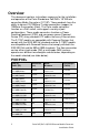
Overview This document contains instructions necessary for the installation and operation of the Perle Standalone PoE/PoE+ 10/100 rate converting Media Converters (S-110P). These products have the ability to convert 10/100Base-T cable connections (copper) to 100Base-X connection (fiber). The Perle media converters function as a PoE switch, and support a variety of port configurations.
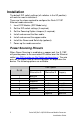
Installation The default DIP switch settings (all switches in the UP position) will work for most installations. These are the steps required to configure the Perle S-110P Ethernet media converter: 1. Insert SFP Module (SFP Model only). 2. Set the DIP switch settings (if required). 3. Set the Powering Option Jumpers (if required). 4. Install and connect the fiber cable. 5. Install and connect the copper cable. 6. Install the Power cord Relief clip (optional). 7. Power up the media converter.
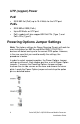
UTP (copper) Power PoE • IEEE 802.3af (PoE) up to 15.4 Watts for the UTP port. PoE+ • IEEE 802at-2009 (PoE+) • Up to 30 Watts on UTP port • PoE+ models will also support 802.3af PDs (Type 1) and PoE+ PDs (Type 2) Powering Options Jumper Settings Note: The factory settings for Power Sourcing Pinouts will work for most installations as 802.3a and 802at-2009 ( POE/POE+) devices will detect and sync to the correct POE option.
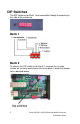
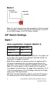
DIP Switches The DIP switches for Bank 1 are accessible through the opening in the side of the enclosure. Bank 1 Bank 2 To access the DIP switches for Bank 2, unscrew the six side screws on the case and remove the cover plate. Locate the jumper set as detailed below.
Bank 2 Note: All switch changes take effect immediately. Switch changes will cycle power to the PD only if the PD Reset switch is set to On or you make changes to the PSE Power switches. DIP Switch Settings Bank 1 Auto-negotiation (copper) (Switch 1) Switch Position Copper Port Up (default) Auto Down Off Note: Auto-negotiation should only be turned off, if the copper link partner does not support Auto-negotiation and fixed settings are required by the copper link partner.
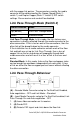
with the copper link partner. The parameters used by the media converter will be determined by the Copper Speed (Bank 2 switch 1) and Duplex Copper (Bank 2 - switch 2) DIP switch settings. Pause receive and send will be disabled. Link Pass-Through Mode (Switch 2) Switch Position Mode Up (default) Link Pass-Through Mode Down Standard Mode Link Pass-Through Mode: In this mode, the link state on one connection is directly reflected through the media converter to the other connection.
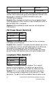
4. (B) Drops link on copper connection because Link PassThrough is configured. 5. (A) Link on copper connection is not affected because Link Pass-Through Mode is set to Standard. Far End Fault (Switch 3) Switch Position Fiber Port Up (default) Enabled Down Disabled Enabled: If the media converter detects a loss of signal on the fiber receiver, it will immediately disable its fiber transmitter signal on the same port.
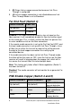
detection Down Down PSE disabled These switches must be set in order to enable the power sourcing function and to indicate the type of device detection required. If the device type is unknown, the default should be used as per IEEE802.3af/at standards. Enabled: When enabled, the media converter will perform Power Sourcing Equipment (PSE) functions as per IEEE802.3af (POE) or 802.3at-2009 (POE+) standards. Disabled: When disabled the media converter will not perform PSE functions.
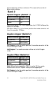
powered devices will be maintained. This mode will override all other switch settings. Bank 2 Speed Copper (Switch 1) Switch Position Copper port Up (default) 100 Down 10 100: When Switch 1 is in the Up position, the S-110P will force the speed to 100 Mbps. 10: When Switch 1 is in the Down position the media converter will force the speed to 10 Mbps.
Half Duplex: The media converter will be set to Half Duplex mode. Auto/MDIX (Switch 4) Switch Position Copper port Up (default) Auto Down MDIX Auto: In the Up switch position; the media converter will automatically detect the Ethernet cable’s polarity. MDIX: The S-110P will operate as a MDIX device. Installing the SFP Fiber Module SFP models only. 1. Locate the appropriate fiber module and insert the SFP into the opening on the front of the media converter. 2.
Installing the Simplex Fiber Cable • Locate a 100BASE-X compliant simplex (1 strand) fiber cable with appropriate connectors. Ensure that the TX wavelength matches the RX wavelength at the other end and the RX wavelength matches the TX wavelength at the other end. • Connect the fiber cable from one media converter to the other media converter/switch/fiber device. Installing the Copper Cable • Locate 10/100Base-T compliant copper cables with the appropriate connectors.
5. Plug the other end of the power cord into an appropriate power outlet. Powering up the Perle Media Converter • Connect the Perle supplied power adapter to the media converter. • Connect the power adapter to a power source. • Check that the PWR LED is lit.
Operation Status LED The Perle PoE/PoE+10/100 Rate converting Media converters have status LEDs located on the front panel of the unit. PWR On – Power is applied to the unit Blinking (slow) – Loopback mode - fiber interface is in loopback mode Blinking (fast) Power On failure.
100- (Copper Port) On – 100 Mbps (valid link and detected speed is 100 Mbps) Off – 10 Mbps (if link is currently established) LKC- (Link Status on Copper port) On – Copper link is present Off – No copper link present Blinking (fast) – Copper link up and receiving data PSE Solid Green (Active) – The PSE has successfully detected a compliant PD and is applying power over UTP. Solid Orange (Inactive) – The PSE is not active.
Other Features Auto-MDIX Auto-MDIX (automatic medium-dependent interface crossover) detects the signalling on the 10/100BASE-T interface to determine the type of cable connected (straight-through or crossover) and automatically configures the connection. Pause (IEEE 802.3xy) Integrated Pause signalling is an IEEE feature that temporarily suspends data transmission between two devices in the event that one of the devices becomes overwhelmed with data.
Troubleshooting General • Ensure power is supplied to the media converter. Only the Perle provided power supply may be used. • Ensure the remote device’s fiber connection type is compatible with the media converter. If using a simplex fiber connection, ensure that you have both an Upstream (U) and Downstream (D) media converter. • Ensure all cabling is of the correct type and is in good working order.
back and passed through the fiber, back to the local converter and passed to the copper link. No Power to the PD • Ensure that the PD is compatible with the S-110P. If the PD is a POE+ device then a POE+ media converter must be used (S-110PP) • Ensure that the power supply being used is the one provided with the product • If the PD does not support Alternative A (including Legacy PD’s), the Power Option Jumpers must be set accordingly. Also ensure the correct pin out for the device.
Technical Specifications The following applies to all S-110P media converters: Power Input / Consumption: 48V DC to 56V DC @ 6 W Operating Temperature: 0°C to 50°C (32°F to 122°F) Storage Temperature: -25°C to 70°C (-13°F to 158°F) Operating Humidity: 5% to 90% non-condensing Storage Humidity: 5% to 95% non-condensing Operating Altitude: Up to 3,048 m (10,000 ft) Dimensions: 80 mm by 120 mm by 26 mm MTBF No Power supply POE POE+ 1 SFP / 1 copper ports 437,237 hours 229,220 hours 81,386 h
S-110P-S2ST120 S-110PP-S2ST120 SM TX: 1550 RX: 1550 Min: 0 Max: 5 Min: -35 Max: 0 35 S-110P-S1SC20U S-110PP-S1SC20U SM TX: 1310 RX: 1550 Min: -14 Max: -8 Min: -32 Max: -3 18 S-110P-S1SC20D S-110PP-S1SC20D SM TX: 1550 RX:1310 Min: -14 Max: -8 Min: -32 Max: -3 18 S-110P -S1SC40U S-110PP -S1SC40U SM TX: 1310 RX:1550 Min: -8 Max: -3 Min: -33 Max: -3 25 S-110P -S1SC40D S-110PP -S1SC40D SM TX: 1550 RX:1310 Min: -8 Max: -3 Min: -33 Max: -3 25 S-110P-SFP S-110PP-SFP SFP Note 1 Note
Compliance Information FCC This product has been found to comply with the limits for a Class A digital device, pursuant to Part 15 of the FCC rules. These limits are designed to provide reasonable protection against harmful interference when the equipment is operated in a commercial environment. This equipment generates, uses, and can radiate radio frequency energy and, if not installed and used in accordance with the instructions in this Guide, may cause harmful interference to radio communications.
Warranty / Registration Perle’s standard Lifetime Warranty provides customers with return to factory repairs for Perle products that fail under the conditions of the warranty coverage. Details can be found at: http://www.perle.com/support_services/warranty.shtml Contacting Technical Support Contact information for the Perle Technical Assistance Center (PTAC) can be found at the link below. A Technical Support Query may be made via this web page. www.perle.com/support_services/support_request.