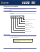
SPEED LE and SPEED LE Express Serial Adapters User Guide Part number: 5500174-14 Date: 11 September 2008 Navigating around this manual Using this on-line manual. See page 5. Fast Contents. See page 7. Contents. See page 8. Index. See page 60.
Copyright statement This document must not be reproduced in any way whatsoever, either printed or electronically, without the consent of: Perle Systems Limited 60 Renfrew Drive Markham, Ontario, Canada L3R 0E1 Perle reserves the right to make changes without further notice, to any products to improve reliability, function or design. JETSTREAM, JETSTREAM4000, JETSTREAM8500 and LANSTREAM2000 are trademarks of Perle Systems Limited.
FCC Note The products described in this manual have been found to comply with the limits for a Class A digital device, pursuant to Part 15 of the FCC rules. These limits are designed to provide reasonable protection against harmful interference when the equipment is operated in a commercial environment. This equipment generates, uses and can radiate radio frequency energy and, if not installed and used in accordance with the instructions in this Guide, may cause harmful interference to radio communications.
SPEED LE and SPEED LE Express Serial Adapters User Guide About this manual Purpose of this manual This manual tells you how to install, configure and use the Perle SPEED LE and SPEED LE Express serial adaptor cards, cabling hardware, associated drivers and utilities. Who this manual is for This manual is aimed at users who want to add extra serial ports to their system using SPEED LE or SPEED LE Express serial adaptor cards.
Using this on-line manual The following is a brief guide to using this manual on-line.
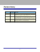
Revision history Date Part number Description December 2005 5500174-10 First issue of the SPEED LE user manual. March 2007 5500174-11 Added instructions for a new Windows 2000/XP/Server 2003/Vista installation process. There are now three Windows drivers to support 32-bit, 64-bit x64, and 64-bit Itanium operating systems/processors. February 2008 5500174-12 Updated guide to support SPEED LE Express cards.
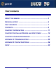
SPEED LE and SPEED LE Express Serial Adapters User Guide Fast Contents ABOUT THIS MANUAL ........................................................... 4 REVISION HISTORY ............................................................... 6 FAST CONTENTS .................................................................. 7 CONTENTS ........................................................................... 8 CHAPTER 1 INTRODUCTION ..................................................
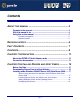
SPEED LE and SPEED LE Express Serial Adapters User Guide Contents ABOUT THIS MANUAL ............................................................ 4 Purpose of this manual ..................................................................................4 Who this manual is for ...................................................................................4 Using this on-line manual ..............................................................................5 Document navigation ......................
Installing under Linux .....................................................................................23 General Installation Procedure for Linux...................................................23 Installing Drivers onto Your System ..........................................................23 Install from Source RPM ................................................................................ 24 Install from Tar File Driver Version 3.4.x or Below .........................................
APPENDIX A: TROUBLESHOOTING.......................................... 53 Windows 2000/XP/Server 2003/Vista/Server 2008 ....................................54 General Troubleshooting under Windows 2000/XP/Server 2003/Vista/ Server 2008 ..............................................................................................55 Windows Error Messages .........................................................................55 APPENDIX B: CONTACTING PERLE ........................................
Chapter 1 Introduction You need to read this chapter if you want to... You need to read this chapter if you want an introduction to the SPEED LE or SPEED LE Express serial adaptor cards, driver software, and utilities. This chapter provides introductory information about the Perle SPEED LE and SPEED LE Express serial adaptor cards, driver software, and configuration utilities.
About the SPEED LE Serial Adaptor cards The SPEED LE and SPEED LE Express Serial Adaptor cards are multi-port cards which provide extra serial ports for EIA-232, peripherals. These cards plug into your PC servers and provide 1, 2, 4, or 8 high speed ports suitable for remote access, data collection, point of sale, or any other EIA-232 applications. You use the SPEED LE and SPEED LE Express serial adaptor cards when you want a robust entry level solution for the small office or point of sale applications.
Connection Accessories The connector box or cable required for the SPEED LE products you are using depends on the number of ports and product type. For details see Chapter 3 Cabling Information.
Chapter 2 Installing Drivers and Host Cards You need to read this chapter if you want to... You need to read this chapter if you want to install SPEED LE or SPEED LE Express serial adaptor cards, associated hardware, and software. This chapter provides information about installing and configuring SPEED LE and SPEED LE Express serial adaptor cards. Note The procedure for installing and configuring SPEED LE or SPEED LE Express serial adaptor cards varies for different operating systems.
Before You Start Before you install your SPEED LE or SPEED LE Express host cards and software, note that the procedure for installing and configuring SPEED LE or SPEED LE Express serial adaptor cards varies for different operating systems.
Downloading Drivers From the Perle Website You can install the SPEED LE or SPEED LE Express driver and utility software from the Perle website. To do this proceed as follows; 1. On your PC, start the Internet browser you want to use. 2. Within your Internet browser window, select the software directory using the following URL; http://www.perle.com/downloads Note In the event of any problems contact your System Administrator or Internet Service provider for assistance. 3.
Installing under Windows 2000/XP/Server 2003/Vista/ Server 2008 This section describes how to install the SPEED LE or SPEED LE Express driver software under Microsoft Windows 2000, XP, Server 2003, Vista, or Server 2008.
Installing Device Drivers and Utilities onto Your System To install or enable the SPEED LE or SPEED LE Express device drivers on your system proceed as follows: 1. Turn on your PC and if required, log in. If you have installed any new SPEED LE or SPEED LE Express cards, a Found New Hardware message is shown, followed by the Found New Hardware wizard as shown. 2. In the Found New Hardware wizard click on the Cancel button. 3.
4. Unzip the driver zip file to a local directory. We recommend that you use the pserial-setup-.exe file, which will launch the installation wizard, to install the SPEED LE driver. 5. Double-click the pserial-setup-.
6. During the installation, you may get a Windows Logo message. Click Continue Anyway when these appear. Note If you are installing an unsigned driver, you may have to click through the Found New Hardware wizard for every SPEED LE or SPEED LE Express port on your system. Your SPEED LE or SPEED LE Express driver installation is now finished.
Configuring Serial Ports To configure SPEED LE or SPEED LE Express serial ports under Windows 2000, XP, Server 2003, Vista, or Server 2008 proceed as follows: 1. In the Windows desktop, click on the Start button and select Settings > Control Panel The control panel window is now displayed. 2. In the Control Panel window, click on the System icon. The System Properties tabbed window is now displayed. 3. In the System Properties window, click on the Hardware tab. The hardware page is now displayed. 4.
5. In the Device Manager window, click on the Multiport serial adapters icon to display the currently installed devices. 6. In the Device Manager window, double click on the device whose properties you want to view or change The device Properties tabbed window is now displayed. 7. In the device Properties window, click on the Port Settings tab to display the Port Settings page. 8. In the Port Settings page, set the Port Number, Baud Rate, and any other configuration parameters you require.
Installing under Linux This section tells you how to install host cards, software drivers, and utilities under the Linux operating system and includes the following: • General Installation Procedure for Linux on page 23 • Installing Drivers onto Your System on page 23 • Creating Devices for the Attached Ports on page 25 General Installation Procedure for Linux The general procedure for installing and configuring host cards, driver software and associated utilities for the Linux operating system is as
Install from Source RPM 1. Log in to the LINUX system as root user. Notes: The path name in the following instructions will be different depending on the LINUX distribution you have installed. ( i.e. Redhat will have a “redhat” directory; Suse will have a “packages” directory) The will change depending on the version of the RPM utilities installed. For newer versions (i.e. 4.2) , the is “rpmbuild”. For older versions use “rpm”. 2.
Install from Tar File Driver Version 3.5.x or Higher 1. Log in to the LINUX system as root user. 2. At the LINUX prompt, copy the supplied perle-serial .tgz file onto your system in the /tmp directory. 3. Unpack the file using the command: tar –xzvf perle-serial--.tgz 4. In the directory run: make Note: If the parallel port driver has been installed, then the system will need to be rebooted to complete the uninstall proces.
Setting the DSR Signal The setultrap utility can be used to configure the DSR Always On option. This feature is used for systems where the wiring does not support the DSR signal but the Host application still requires that the DSR be active. When the DSR Always On option to set to "on," the driver will always report to the application that the DSR signal is "on".
Installing Host Cards and Cable Accessories This section describes the mechanical installation of the SPEED LE and SPEED LE Express host cards and associated connector boxes and cables for 1,2, 4, and 8 ports and includes the following; • Installing SPEED LE and SPEED LE Express Cards on page 27 • Installing Cables and Connector Boxes on page 28 Installing SPEED LE and SPEED LE Express Cards This section describes the mechanical installation of SPEED LE and SPEED LE Express cards.
3. Insert the SPEED LE or SPEED LE Express card you want to install into a vacant host PCI card slot and secure in place as shown in the next picture. Caution Full anti-static precautions should be taken when handling host cards. 4. Repeat step 3. until you have installed all the SPEED LE or SPEED LE Express cards you want. 5. Replace and secure the system cover. Installation of SPEED LE or SPEED LE Express cards is now complete.
Installing Fan-out Cables and Connector Boxes on SPEED4 LE HD and SPEED8 LE HD Cards SPEED4 LE HD and SPEED8 LE HD cards have a single VHDCI-68 connector on the back panel. It provides the signals for 4 or 8 serial ports. A fan-out cable or connector box with the proper individual connectors can be plugged into the card to provide the desired interface. The port numbers will be identified on the interface connectors or connector box.
Removing Host Cards To remove any SPEED LE or SPEED LE Express card from your system, proceed as follows; Note The exact location of host card slots varies for different systems, for exact mechanical details of your system, refer to your system documentation. Warning Dangerous voltages exist inside computer systems. Before removing host cards from your system, turn off the power supply and unplug the power cord. 1. Turn off the power to your system and unplug the power cord. 2.
Chapter 3 Cabling Information You need to read this chapter if you want to... You need to read this chapter if you want cabling information for the SPEED LE and SPEED LE Express serial adaptor cards. This chapter provides cabling and connector pinout information for the SPEED LE and SPEED LE Express serial adaptor cards. Included are details of standard cables for use with SPEED LE and SPEED LE Express products available from Perle.
Definitions of Signals and Direction EIA-232 Direction Description RI In Ring Indicator DCD In Data Carrier Detect RTS Out Request To Send DSR In Data Set Ready TXD Out Transmit Data RXD In Receive Data S-GND Signal Ground CTS In Clear to Send DTR Out Data Terminal Ready C-GND Chassis Ground Definitions of Signals and Direction Page 32
DB9 Back Panel Connectors and Pinout The following diagram shows the SPEED1 LE and SPEED LE Express standard and Low Profile back panels respectively.
Host Card Back Panel Connectors and Pinouts This section contains diagrams and pinout information for the SPEED LE and SPEED LE Express host card back panel connectors contains the following; DB9 Back Panel Connectors and Pinout on page 33 SPEED LE RJ45 Back Panel Connectors and Pinout on page 35 SPEED LE Express RJ45 Back Panel Connectors and Pinout on page 36 VHDCI-68 Ultra SCSI Back Panel Connectors and Pinout on page 38 Host Card Back Panel Connectors and Pinouts Page 34
SPEED LE RJ45 Back Panel Connectors and Pinout The following diagram shows the SPEED2 LE and SPEED4 LE RJ-45 cards back panel. The RJ45 connector has a 10-pin configuration. If you require an 8-pin connector configuration, use the pinouts in the RJ45 8-pin column.
SPEED LE Express RJ45 Back Panel Connectors and Pinout The following diagram shows the SPEED2 LE Express and SPEED4 LE Express RJ-45 cards back panel. The RJ45 connector has a 10-pin configuration. If you require an 8-pin connector configuration, use the pinouts in the RJ45 8-pin column.
DB25 Femaie Parallel Port Pinouts The SPEED LE and SPEED LE Express parallel port pinouts are provided below for cards that support the parallel port. DB25 Pin Cent Pin Direction Signal Name Function Notes 1 1 out -Strobe Set Low p1ulse >0.
VHDCI-68 Ultra SCSI Back Panel Connectors and Pinout The following diagram shows the SPEED4 LE HD Low Profile and standard back panels respectively.
VHDCI-68 Ultra SCSI Pin Number EIA-232 9 S-GND 10 TXD3 11 DSR3 12 DTR3 13 DCD3 14 RTS3 15 RI3 16 CTS3 17 RXD3 18 RXD2 19 CTS2 20 RI2 21 RTS2 22 DCD2 23 DTR2 24 DSR2 25 TXD2 26 S-GND 27 TXD1 28 DSR1 29 DTR1 30 DCD1 31 RTS1 32 RI1 33 CTS1 34 RXD1 35-42 NC 43 S-GND 44-59 NC 60 S-GND 61-68 NC Host Card Back Panel Connectors and Pinouts Page 39
The following diagram shows the SPEED8 LE HD standard and Low profile back panels respectively The connector pinout for each VHDCI-68 Ultra SCSI connector fitted to the SPEED8 LE HD, Low profile are as follows; Ports 1-8 of VHDCI-68 Connector for SPEED8 LE HD adapter cards VHDCI-68 Ultra SCSI Pin Number EIA-232 1 RXD7 2 CTS7 3 RI7 4 RTS7 5 DCD7 6 DTR7 7 DSR7 8 TXD7 9 S-GND 10 TXD5 11 DSR5 12 DTR5 Host Card Back Panel Connectors and Pinouts Page 40
VHDCI-68 Ultra SCSI Pin Number EIA-232 13 DCD5 14 RTS5 15 RI5 16 CTS5 17 RXD5 18 RXD3 19 CTS3 20 RI3 21 RTS3 22 DCD3 23 DTR3 24 DSR3 25 TXD3 26 S-GND 27 TXD1 28 DSR1 29 DTR1 30 DCD1 31 RTS1 32 RI1 33 CTS1 34 RXD1 35 RXD8 36 CTS8 37 RI8 38 RTS8 39 DCD8 40 DTR8 41 DSR8 42 TXD8 43 S-GND Host Card Back Panel Connectors and Pinouts Page 41
VHDCI-68 Ultra SCSI Pin Number EIA-232 44 TXD6 45 DSR6 46 DTR6 47 DCD6 48 RTS6 49 RI6 50 CTS6 51 RXD6 52 RXD4 53 CTS4 54 RI4 55 RTS4 56 DCD4 57 DTR4 58 DSR4 59 TXD4 60 S-GND 61 TXD2 62 DSR2 63 DTR2 64 DCD2 65 RTS2 66 RI2 67 CTS2 68 RXD2 Host Card Back Panel Connectors and Pinouts Page 42
Connector Box and Cable Guide The connector pinout information for the SPEED LE product you are using depends on the number of ports and type of connector box or cable used as detailed in the next table; Product Card edge connector Cable or connector box options For connector pinouts see...
Connector Box and Cable Pinouts This section contains pinout information for the SPEED LE product range connector box and cable accessories and contains the following; • RJ45 10-pin to DB25 Converter on page 45 • RJ45 10-pin to DB9 Converter on page 46 • RJ45 Connector Box on page 47 • DB25 Connector Box on page 48 • DB9 Connector Box on page 49 • DB25 Fan-Out Cable on page 50 • DB9 Fan-Out Cable on page 51 Note For details of which cables to use with which product, see Connector Box and Cable
RJ45 10-pin to DB25 Converter RJ45 pin DB25 Pin EIA-232 DIRECTION 1 22 RI IN 2 8 DCD IN 3 20 DTR OUT 4 6 DSR IN 5 7 GND 6 2 TXD OUT 7 3 RxD IN 8 4 RTS OUT 9 5 CTS IN 10 N/C 1 & Shell 1 & Shell C-GND Connector Box and Cable Pinouts Page 45
RJ45 10-pin to DB9 Converter RJ45 pin DB9 Pin EIA-232 DIRECTION 1 9 RI IN 2 1 DCD IN 3 4 DTR OUT 4 6 DSR IN 5 5 GND 6 3 TXD OUT 7 2 RXD IN 8 7 RTS OUT 9 8 CTS IN 10 N/C Shell Shell C-GND Connector Box and Cable Pinouts Page 46
RJ45 Connector Box Connect peripheral cable here via RJ45 RJ45 connector block Push fit onto card edge connector Note The SPEED LE connector box cable needs to be secured or supported in case of sudden contact or excessive weight on the cables. Please ensure that adequate caution is taken to avoid possible damage to the SPEED LE card or Host system. This can be accomplished by securing the cable to a rack or to the back of the server.
DB25 Connector Box Note The SPEED LE connector box cable needs to be secured or supported in case of sudden contact or excessive weight on the cables. Please ensure that adequate caution is taken to avoid possible damage to the SPEED LE card or Host system. This can be accomplished by securing the cable to a rack or to the back of the server.
DB9 Connector Box Note The SPEED LE connector box cable needs to be secured or supported in case of sudden contact or excessive weight on the cables. Please ensure that adequate caution is taken to avoid possible damage to the SPEED LE card or Host system. This can be accomplished by securing the cable to a rack or to the back of the server.
DB25 Fan-Out Cable Port numbers labelled on DB25 connectors Push fit onto card edge connector Connect peripheral cable here Note The SPEED LE fan-out cables need to be secured or supported in case of sudden contact or excessive weight on the cables. Please ensure that adequate caution is taken to avoid possible damage to the SPEED LE card or Host system. This can be accomplished by securing the cables to a rack or to the back of the server.
DB9 Fan-Out Cable Note The SPEED LE fan-out cables need to be secured or supported in case of sudden contact or excessive weight on the cables. Please ensure that adequate caution is taken to avoid possible damage to the SPEED LE card or Host system. This can be accomplished by securing the cables to a rack or to the back of the server.
Low Profile Bracket Conversion The SPEED LE and SPEED LE Express cards come fitted with standard brackets. Additional low profile brackets are included with your SPEED LE and SPEED LE Express cards to accomodate low profile servers. This section describes how to convert your SPEED LE and SPEED LE Express cards from standard to low profile brackets. To convert a standard profile bracket to a low profile bracket(s) and install it, do the following: 1.
Appendix A: Troubleshooting You need to read You need to read this appendix if you want information on troubleshooting problems with this appendix if you SPEED LE or SPEED LE Express serial adaptor cards. want to... This appendix provides examples of normal boot up messages and a table of error messages, their meaning and corrective action required for the all the currently supported operating systems. This appendix includes the following section, Windows 2000/XP/Server 2003/Vista/Server 2008 on page 54.
Windows 2000/XP/Server 2003/Vista/Server 2008 This section describes troubleshooting SPEED LE products under the Windows 2000, Windows XP, Windows Server 2003, Windows Vista, or Windows Server 2008 operating systems and includes the following sections; Note To contact Perle for technical support, see Appendix B: Contacting Perle. • General Troubleshooting under Windows 2000/XP/Server 2003/Vista/Server 2008 on page 55. • Windows Error Messages on page 55.
General Troubleshooting under Windows 2000/XP/Server 2003/Vista/Server 2008 Problem Action required Machine fails to boot. 1. Turn off your machine, remove SPEED LE card(s) and reboot. See page 30. 2. Try installing a different host card in case the one currently installed is faulty. See page 27. Windows operating system fails while loading and the system hangs. 1. Reboot machine and then switch to the last known good configuration. 2. Check for resource conflicts or faulty hardware.
Appendix B: Contacting Perle You need to read You need to read this appendix if you want to contact Perle for technical support or any other this appendix if you queries about this product. want to... This appendix includes the following sections; • Making a technical support query on page 56 • Repair procedure on page 58 • Feedback about this manual on page 58 • Perle support centres worldwide on page 59 Internet access Click here to access the our website at the following URL: http://www.perle.
Information needed when making a query When you make a technical support enquiry please have the following information ready; Hint Print out this page and fill in the table provided with the basic information you need.
Making a support query via the Perle web page If you have an internet connection, please send details of your problem to Technical Support using the email links provided on the Perle web site in the ‘Support’ area. See also Perle support centres worldwide on page 59 for email links and other contact details for the Perle technical support centres. Click here to access our website at the following URL: http://www.perle.
Perle support centres worldwide Note Perle offers free technical support to Perle Authorised Distributors and Registered Perle Resellers. To access technical support please visit the Perle website at www.perle.com/support_services/index.shtml. If you are unable to find the information you require, please feel free to contact our technical support teams by email using the addresses shown in the next table. Country Address Email North America Perle Systems Ltd.
#A B C D E F G H I J K L M N O P Q R S T U V W X Y Z Index Numerics F 4 port cards installing 27 Fast Contents.
#A B C D E F G H I J K L M N O P Q R S T U V W X Y Z P product repair form 58 R removing host cards 30 repair procedure 58 product repair form 58 RMA form 58 RJ45 socket card edge views 32 pinouts 32 RMA form 58 S serial ports configuring under Windows 21 T technical support 56 centres worldwide 59 queries, information needed for 57 via the internet 58 who to contact 56 troubleshooting Windows 54 W Windows 18 configuring serial ports 21 device drivers and utilities installing 18 installing device driver