Perle IDS-105G (XT) Unmanaged 10/100/1000 Ethernet Switches Installation Guide P/N 5500340-10
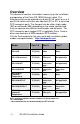
Overview This document contains instructions necessary for the installation and operation of the Perle IDS-105G Ethernet switch. This Ethernet switch can be ordered as a 5-port RJ-45 switch or as a 5port RJ-45 switch with either one fiber port (SC or ST) or up to two SFP transceiver ports. The fiber port can be either single mode (SM) or multimode (MM) depending on the model selected and they can operate over different wavelengths and distances.
Features • • • • • • • • • 10/100/1000Base-T, 1000Base-X, SC/ST/SFP fiber ports, multi/single mode Pluggable SFP transceiver ports IEEE 802.3/802.3u/802.
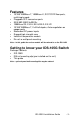
Front View of IDS-105G (5 port RJ-45) -4- IDS-105G Installation Guide
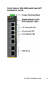
Front View of IDS-105G (with two SFP transceiver ports) IDS-105G Installation Guide -5-
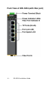
Front View of IDS-105G (with fiber port) -6- IDS-105G Installation Guide
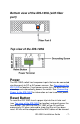
Bottom view of the IDS-105G (with fiber port) Top view of the IDS-105G Power The IDS-105G switch has two power inputs that can be connected simultaneously to DC or AC power sources. See Top view of the IDS-105G for location. If one power source fails, the other acts as a backup, and automatically powers the switch. See Connecting Power to the IDS-105G for information on how to connect power.
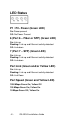
LED Status P1 / P2– Power (Green LED) On: Power present Off: No Power Present 6 (Port 6 – Fiber or SFP) (Green LED) On: Link up Flashing: Link up and Ethernet activity detected Off: Link down 7 (Port 7 – SFP) (Green LED) On: Link up Flashing: Link up and Ethernet activity detected Off: Link down Port Link (Green and/or Yellow LED) On: Link up Flashing: Link up and Ethernet activity detected Off: Link Down Port Speed (Green and Yellow LED) 1000 Mbps:Green On; Yellow Off 100 Mbps:Green On; Yellow On 10 M
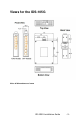
Views for the IDS-105G Note: all dimensions are in mm IDS-105G Installation Guide -9-
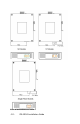
Note: all dimensions are in mm - 10 - IDS-105G Installation Guide
Mounting the IDS-105G on a DIN-rail 1. The DIN-rail clip will be fixed to the back panel of the IDS105G switch when you receive the product. 2. Position the IDS-105G switch such that the top of the DIN-rail fits into the slot on the top of the DIN-rail clip, just below the hook and behind the spring. 3. While pushing down on the unit to compress the spring rotate the bottom of the IDS-105G toward the rail. This will snap the bottom of the rail into the bottom of the clip. See diagram below.
Mounting the IDS-105G to the Wall 1. Remove the DIN-rail clip from the rear panel on the IDS-105G. 2. Attach the wall mount plates to the IDS-105G switch as shown below using the screws provided in the kit. 3. Use the wall mount plates as a guide to mark the spots where the screws will be. 4. Drive the screws into the wall leaving about 2 mm of the screw protruding from the wall to allow room for sliding the wall mount panel between the wall and the screws. 5.
Wiring up the IDS-105G Power sources must be off prior to beginning the power connection steps. Ensure that the voltage and current ratings of the intended power source are appropriate for the IDS105G as indicated on the product label. Ensure that the installation and electrical wiring of the equipment is performed by trained and qualified personnel and that the installation complies with all local and national electrical codes.
Connecting the IDS-105G to ground If your installation requires additional grounding follow this procedure. 1. Follow the manufacturer’s instructions for attaching the ground wire to grounding lug. 2. Attach the grounding lug to the chassis and secure with the grounding screw provided. Grounding the chassis requires the following items: • • One grounding lug (not provided) One 18-12 AWG wire (not provided) Connecting Power to the IDS-105G 1. Ensure the power source is off prior to connection. th 2.
Ethernet Copper Cabling Requirements • • • Category 5 UTP or STP 24-22 AWG Straight through or Ethernet crossover cable Connect the copper cables from each TP port (RJ-45) on the IDS105G switch to Ethernet-enabled devices. See below for pinouts. 8-pin RJ-45 Remaining pins not used. Fiber Port Cabling Requirements MM: 50/125 microns or 62.5/125 microns SM: 9/125 microns Connect the fiber cables to Port 6/7 on the IDS-105G and the other end to a compliant fiber devices.
Technical Specifications Connection Dual input terminal block power Reverse Polarity Protection Power Input/Consumption 9.6 to 60 VDC, 1.25Amax 18 to 30 VAC, 0.
None IDS-105G-DSFP* (XT) n/a n/a n/a n/a n/a one - - - - - - None two - - - - - - IDS-105G-M2SC05 (XT) SC None MM duplex 550 m 1804 ft TX: 850 RX:850 Min:-9.5 Max:-4 Min:-17 Max:-3 7.5 IDS-105G-M2ST05 (XT) ST None MM duplex 550 m 1804 ft TX: 850 RX:850 Min:-9.5 Max:-4 Min:-17 Max:-3 7.5 IDS-105G-M2SC2 SC None MM duplex 2 km 1.2 miles TX: 1310 RX:1310 Min:-6 Max:0 Min:-17 Max:-3 11 IDS-105G-M2ST2 ST None MM duplex 2 km 1.
IDS-105G-S2SC40 SC None SM duplex 40 km 24.9 miles TX: 1310 RX:1310 Min:-3 Max:-5 Min:-23 Max:-3 20 IDS-105G-S2ST40 ST None SM duplex 40 km 24.9 miles TX: 1310 RX:1310 Min:-3 Max:-5 Min:-23 Max:-3 20 IDS-105G-S1SC40U SC None SM duplex 40 km 24.9 miles TX: 1310 RX:1490 Min:-3 Max:-2 Min:-23 Max:-3 20 IDS-105G-S1SC40D SC None SM duplex 40 km 24.9 miles TX: 1490 RX:1310 Min:-3 Max:-2 Min:-23 Max:-3 20 IDS-105G-S2SC70 SC None SM duplex 70 km 43.
Contacting Technical Support Contact information for the Perle Technical Assistance Center (PTAC) can be found at the link below. A Technical Support Query may be made via this web page. www.perle.com/support_services/support_request.shtml Warranty / Registration This product is covered by the Perle Ethernet Switches Warranty. Details can be found at: http://www.perle.com/support_services/warranty.shtml Copyright © 2014 Perle Systems Limited all rights reserved.