CR SERIES INSTALLATION INSTRUCTIONS PERLICK COLLECTION 24” AND 30” COLUMN REFRIGERATION To prevent appliance damage and injury, read these instructions thoroughly prior to installation. FORM NO. Z2496 REV.
PERLICK RESIDENTIAL COLUMN REFRIGERATION INSTALLATION INSTRUCTIONS CONTENTS INTRODUCTION Congratulations on your purchase of a Perlick Collection column refrigeration appliance. This manual has been prepared to assist you in the installation of your column refrigerator, freezer and wine reserve.
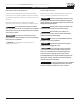
PERLICK RESIDENTIAL COLUMN REFRIGERATION INSTALLATION INSTRUCTIONS SAFETY CONSIDERATIONS IMPORTANT SAFETY INFORMATION SAFETY PRECAUTIONS Please review the following safety precautions and read all instructions prior to product installation. After the completion of installation, keep these instructions in a safe place for future reference. Please take note of the following safety precautions prior to moving, unpacking and installing your Perlick column.
PERLICK RESIDENTIAL COLUMN REFRIGERATION INSTALLATION INSTRUCTIONS PRIOR TO INSTALLATION PRIOR TO INSTALLATION Before beginning installation, carefully CAUTION inspect the cabinet for hidden damage. If damage is discovered, immediately file a claim with the transportation company. Perlick is not responsible for damage in transit. CAUTION When moving the unit, be sure to protect finished flooring with appropriate material to avoid damage from moving the appliance.
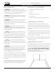
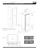
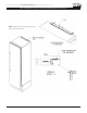
PERLICK RESIDENTIAL COLUMN REFRIGERATION INSTALLATION INSTRUCTIONS NICHE / PRODUCT DIMENSIONS B A PLEASE NOTE: When installing column adjacent to wall, a 2” clearance is required if door is opening towards the wall A CR24 24” (610) CR30 30” (762) B CR24 23 -3/4” (604) CR30 29-3/4” (756) A perlick customer service (800)558-5592 | 5
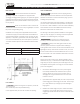
PERLICK RESIDENTIAL COLUMN REFRIGERATION INSTALLATION INSTRUCTIONS ELECTRICAL / ANTI-TIP BRACKET / PRODUCT PLACEMENT ELECTRICAL ANTI-TIP BRACKET Serious electrocultion hazard. Electrical ! DANGER grounding is required. This appliance is equipped with a 3-prong (grounding) polarizing plug for your protection against possible shock hazards. Failure to comply with these electrical guidelines may result in possible death or serious injury, fire or loss of property.
PERLICK RESIDENTIAL COLUMN REFRIGERATION INSTALLATION INSTRUCTIONS LEVELING / ALIGNMENT LEVELING/ALIGNMENT Move the unit near the opening. Plug the power cord into the grounded outlet and roll the unit into position. Push unit into place. Front and rear leveling legs can be adjusted from the front once the unit is positioned. To access leveling adjustment access holes, remove toe kick grill. Once the unit is in position, height adjustment can be made from the front.
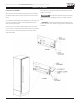
PERLICK RESIDENTIAL COLUMN REFRIGERATION INSTALLATION INSTRUCTIONS ANTI-TIP BRACKET INSTALLATION FOR INTEGRATED INSTALLATION NOTE: Do not fasten anti-tip brackets to adjacent cabinetry until the cabinet has been leveled. 8 | perlick.
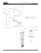
PERLICK RESIDENTIAL COLUMN REFRIGERATION INSTALLATION INSTRUCTIONS ANTI-TIP BRACKET INSTALLATION FOR FREESTANDING INSTALLATION NOTE: Cabinet must be leveled before securing to wall with anti-tip bracket.
PERLICK RESIDENTIAL COLUMN REFRIGERATION INSTALLATION INSTRUCTIONS DOOR / SIDE PANEL INFORMATION DOOR PANELS Perlick column refrigeration comes ready to accept a customer supplied overlay door panel and customer supplied handle. Stainless steel door panels and Perlick handles are also available, and are sold separately of the unit itself. Stainless steel panels and handles can be purchased through an authorized Perlick dealer.
PERLICK RESIDENTIAL COLUMN REFRIGERATION INSTALLATION INSTRUCTIONS CR24 SOLID DOOR TEMPLATE FOR 4” TOE KICK 3 2 1 16 8 " 3 14 8 " 1 24" 3 14" 1 12 2 " 1 36 2 " 3 98" (4X) 5 78" .136 .500 A 3 8" 1 60 2 " OVER 7 79 8 " 3 8" 3 8" (2X) .136 .250 MATERIAL: WOOD 3 64" 11 1 16 " 1 2 16 " 7 11 8 " 5 19 8 " 3 23 4 " C:\Perlick\Engineering\Projects\Refrigeration\1601802\CAD Files\1007916.slddrw 3 QTY.
PERLICK RESIDENTIAL COLUMN REFRIGERATION INSTALLATION INSTRUCTIONS CR30 SOLID DOOR TEMPLATE FOR 4” TOE KICK 12 | perlick.
PERLICK RESIDENTIAL COLUMN REFRIGERATION INSTALLATION INSTRUCTIONS CR24 SOLID DOOR TEMPLATE FOR 6” TOE KICK 2 3 1 16 8 " 3 14 8 " 1 24" 3 98" 3 14" (4X) 5 78" .136 .500 1 12 2 " B 3 8" 1 36 2 " 1 60 2 " 7 77 8 " 3 8" .188 (12X) .250 3 8" (2X) .136 .250 MATERIAL: WOOD 7 48" 3 14" 1 2 16 " 7 11 8 " QTY.: - 5 19 8 " 3 23 4 " 1 2 16 " 3 4" FINISH: THIS DOCUM FORM, ELECTR SW C:\Perlick\Engineering\Projects\Refrigeration\1601802\CAD Files\1007916.
PERLICK RESIDENTIAL COLUMN REFRIGERATION INSTALLATION INSTRUCTIONS CR30 SOLID DOOR TEMPLATE FOR 6” TOE KICK 14 | perlick.
PERLICK RESIDENTIAL COLUMN REFRIGERATION INSTALLATION INSTRUCTIONS CR24 GLASS DOOR TEMPLATE FOR 4” TOE KICK 2 3 1 16 8 " 3 14 8 " 1 24" 3 14" .136 3 98" 5 78" C 3 4" FOR LOCK OPTIONAL USE DRILL FIXTURE TO LOCATE HOLE 3 4" 5 68" 1 12 2 " 1 36 2 " .500 (4X) A 3 8" OVERLAY C 1 60 2 " DE SCA 60" CUTOUT B 3 8" 7 79 8 " 3 8" 3 38" A 17" CUTOUT MATERI WOOD 3 64" 11 1 16 " .136 1 2 16 " TYP 7 11 8 " .500 (2X) QTY.: FINISH: 5 19 8 " TYP 3 23 4 " THIS FORM, SW C:\Perlick\Engineeri
PERLICK RESIDENTIAL COLUMN REFRIGERATION INSTALLATION INSTRUCTIONS CR24 GLASS DOOR TEMPLATE FOR 6” TOE KICK 2 3 1 24" 3 14" C .136 .500 (4X) 3 4" FOR LOCK OPTIONAL USE DRILL FIXTURE TO LOCATE HOLE 3 4" 5 68" 1 12 2 " 1 36 2 " 1 16 8 " 3 14 8 " 3 98" 5 78" A 3 8" .136 .500 (12X) 1 60 2 " 60" CUTOUT B 7 77 8 " 3 8" OVERLAY CLIP DETA SCALE 3 8" 3 38" A 17" CUTOUT MATERIAL WOOD 7 48" 3 14" 1 2 16 " TYP 7 11 8 " QTY.: - 5 19 8 " TYP 3 23 4 " .136 SW C:\Perlick\Engineering\Proje
PERLICK RESIDENTIAL COLUMN REFRIGERATION INSTALLATION INSTRUCTIONS SCREW ZONE FOR CR24 AND CR30 OVERLAY TEMPLATES 2 3 3 23A4 " 1 3 16 " 1 3 16 " 1 34" 3 4" NOTE: HATCH AREAS SHOULD PROVID THICKNESS FOR WOOD SCREW OVERLAY ATTACHMENT BRACK 1 69 2 " 66" NOTE: HATCH AREAS SHOULD PROVIDE ENOUGH THICKNESS FOR WOOD SCREWS FOR OVERLAY MATERIAL: ATTACHMENT BRACKET. WOOD 3" A CR24 CL 3 11B8 " QTY.: 23-3/4” FINISH: 29-3/4” CR30 1" C:\Perlick\Engineering\Projects\Refrigeration\1601802\CAD Files\1007917.
PERLICK RESIDENTIAL COLUMN REFRIGERATION INSTALLATION INSTRUCTIONS INSTALLING DOOR OVERLAY PANELS DOOR PANEL INSTALLATION DOOR OVERLAY PANEL ADJUSTMENT Typical panel dimensions are based on 84” (2134) finished height with 1/8” (3) reveals. Template must be adjusted for panels exceeding typical dimensions. Close the door to make adjustments to align panels and reveals. Place panel face down on a protected work surface.
PERLICK RESIDENTIAL COLUMN REFRIGERATION INSTALLATION INSTRUCTIONS TOP OF DOOR ILLUSTRATION perlick customer service (800)558-5592 | 19
PERLICK RESIDENTIAL COLUMN REFRIGERATION INSTALLATION INSTRUCTIONS DOOR TRIM INSTALLATION AIRFLOW DIVIDER DOOR TRIM INSTALLATION Perlick includes air flow dividers for both 4” and 6” toe kick installations. This frame and gasket is installed to the back of the door panel. Once overlay is adjusted, mount the door trim bracket onto the door adjustment bracket using the provided screws.
PERLICK RESIDENTIAL COLUMN REFRIGERATION INSTALLATION INSTRUCTIONS COMPLETION - GRILL INSTALLATION GRILL INSTALLATION Install the grill by snapping into latch catches.
PERLICK RESIDENTIAL COLUMN REFRIGERATION INSTALLATION INSTRUCTIONS TOE KICK CLEARANCE 22 | perlick.
PERLICK RESIDENTIAL COLUMN REFRIGERATION INSTALLATION INSTRUCTIONS INSTALLING FILTERS CARBON AIR FILTERS ETHYLENE FILTERS Carbon air filters should be placed in the holder in the perforated panel located in the top-rear of the cabinet (A). Ethylene filters should be placed in the holder in top of the tipout produce bin (B). NOTE: When installing carbon air filter in wine units, the top rack will need to be removed to access the perforated panel. 1.
Perlick Residential is a division of Perlick Corporation © 2019 Perlick Corporation 8300 West Good Hope Road, Milwaukee, WI 53223, USA perlick.com/residential • (800) 558-5592 FORM NO. Z2496 REV.