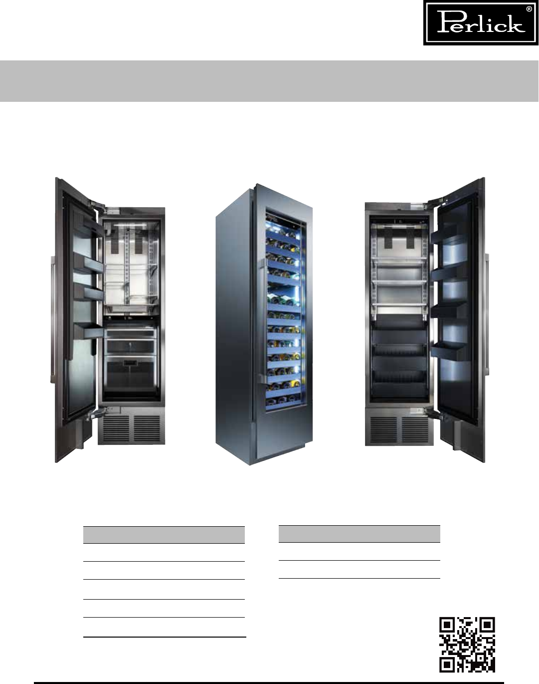
SERVICE MANUAL Column Refrigeration Residential and Commercial CR24R CC24W CR24F Product Series Covered in this Manual: CR24D CR24F CR24R CR24W CR30R Residential Commercial CC24D CC24W Scan here to download a PDF copy of this manual. Form No. Z2551 Rev.
Column Refrigeration Service Manual Table of Contents 1.0 GENERAL INFORMATION......................................................................................... 10 1.1 Use of Service Manual...............................................................................................10 1.2 Model Families..........................................................................................................10 1.3 I.D. Plate ............................................................................
Column Refrigeration Service Manual Table of Contents (cont.) Column Freezer.........................................................................................................30 5.4 Control Alarms..........................................................................................................31 5.5 Refrigerator Control Operation...................................................................................32 5.5.1 Using The Refrigerator Column Control.............................
Column Refrigeration Service Manual Table of Contents (cont.) 6.6 Replace Refrigeration Module.....................................................................................50 6.7 Replace Condenser Fan Motor....................................................................................53 6.8 Replace Evaporator Fan Motor....................................................................................53 6.9 Replace Inverter........................................................................
Column Refrigeration Service Manual Table of Contents (cont.) 8.12.5 24” Glass Door Template For 4” Toe Kick......................................................89 8.12.6 24” Glass Door Template For 6” Toe Kick......................................................90 8.12.7 24” Screw Zone For Overlay Templates.........................................................91 8.12.8 30” Screw Zone For Overlay Templates.........................................................92 8.13 Tip-Out Bin.
Column Refrigeration Service Manual Table of Figures Figure 1-1. Information Plate for Refrigeration Units.......................................................................10 Figure 2-1.1. Danger Fire/Explosion Risk Label...............................................................................12 Figure 2-1.2. Danger Fire/Explosion Risk Servicing Label.................................................................12 Figure 2-1.3. Warning Handling Label...........................................
Column Refrigeration Service Manual Table of Figures (cont.) Figure 6-14.1. Evaporator Fan Motor/Fastener................................................................................53 Figure 6-14.2. Evaporator Terminal Block.......................................................................................53 Figure 6-15.1. Remove Cotter Pins................................................................................................54 Figure 6-15.2. Lift And Rotate Compressor....................
Column Refrigeration Service Manual Table of Figures (cont.) Figure 8-7.2. Hinge Activation Fastener (T-20) (Activated)...............................................................80 Figure 8-8. Removing Gasket........................................................................................................81 Figure 8-9. Removing Door Trim Cover..........................................................................................82 Figure 8-10. Lock Installation.................................
Column Refrigeration Service Manual Table of Tables Table Table Table Table Table Table Table Table Table Table Table Table Table Table Table Table Table Table Table Table Table Table Table Table Table Table 3.1. Refrigeration System Diagnostics/Troubleshooting......................................................13 3.2. Electrical System Diagnostics/Troubleshooting............................................................17 3.3. Doors, Drawers, Shelving Diagnostics/Troubleshooting......................
Column Refrigeration Service Manual 1.0 General Information 1.1 Use of Service Manual This service manual is intended for use by a qualified service technician. It is provided as a guide to diagnose and repair service issues for the product models listed on the cover. If you have any questions or require additional assistance, contact Perlick Customer Service during regular hours of operation. 1.
Column Refrigeration Service Manual 2.0 Safety Information 2.1 Refrigerant HC-600a All self-contained models covered in this service manual are manufactured using refrigerant HC-600a (Isobutane). 2.2 Vacuum pumps must be explosion-safe. It must be possible to lead the discharge air from the vacuum pump into open air. • Leak detection cannot take place with normal halogen leak detectors, as they do not react on hydrocarbons. A special detector reacting on a hydrocarbon must be used instead.
Column Refrigeration Service Manual 2.0 Safety Information 2.4 Product Safety Labels Figure 2-1.6. Warning Transporting Hazard Label Figure 2-1.1. Danger Fire/Explosion Risk Label Figure 2-1.2. Danger Fire/Explosion Risk Servicing Label Figure 2-1.3. Warning Handling Label Figure 2-1.4. Warning Tip-Over Hazard Label Figure 2-1.7. Uncrating Label Figure 2-1.5.
Column Refrigeration Service Manual 3.0 Troubleshooting Guide 3.1 Refrigeration System Use this diagnostic guide to identify issues and to locate applicable instructions within this service manual. This diagnostic guide can be used for any of Perlick’s Back Bar Refrigeration Products. DANGER ELECTROCUTION HAZARD!! Never attempt to repair or perform maintenance on the unit until the Main electrical power has been disconnected.
Column Refrigeration Service Manual 3.1 Refrigeration System (cont.) PROBLEM Not Cooling (cont.) CAUSE SOLUTION Inverter Loose Connection Check Connections Power Ensure 120 power to inverter continuously Signal Circuit Power Ensure Signal Circuit has power Compressor Open Windings Check continuity between pins Locked Rotor Verify locked rotor Internal Damage Verify Amperage Refrigerant Leak See Section 6.11.
Column Refrigeration Service Manual 3.1 Refrigeration System (cont.
Column Refrigeration Service Manual 3.1 Refrigeration System (cont.
Column Refrigeration Service Manual 3.
Column Refrigeration Service Manual 3.2 Electrical System (cont.
Column Refrigeration Service Manual 3.3 Doors, Drawers, Shelving PROBLEM Hinge Problems CAUSE SOLUTION Improper Door Mounting Verify proper mounting. Hinges not activated Activate Hinges Excessive wear Replace Worn Parts Improper Handle Mounting Verify proper mounting.
Column Refrigeration Service Manual 4.0 Electrical Components and Specifications 4.1 Compressor 4.2 Inverter 4.2.1: Drop-In 4.1.1 MODEL: VEMX5C Column Models CC24D, CC24W, CR24D, CR24R, CR24W, CR30R Type Variable Capacity (Speed) Hermetic Reciprocating Compressor Model: EM (Used with VEMX5C Compressor) Input 115-127V AC / 50-60 HZ / 1 Ph / 3.3 A Max Output 230V AC / 40-150 Hz / 3 Ph / 2.
Column Refrigeration Service Manual 4.5 Hot Gas Defrost Solenoid Valve Coil Rating 12VDC, 15W, 1.08A, 11.1 ohms Table 4.5. Hot Gas Defrost Solenoid Valve Specs 4.6 Control Specifications Input 120V AC, 3.3A max Output Various Table 4.6. Control Specs 4.7 Damper Specifications 12VDC, 0.5W, 1850 Step Stepper Motor Table 4.7. Damper Specs 4.
Column Refrigeration Service Manual 5.0 Component Operation 5.
Column Refrigeration Service Manual 5.
Column Refrigeration Service Manual 5.
Column Refrigeration Service Manual 5.
Column Refrigeration Service Manual 5.2 Electrical Specifications Electrical Specifications MODEL 26 POWER TYPE VOLTAGE (V) CURRENT (A) FREQ (Hz) PHASE ELECTRICAL CONNECTION PLUG CC24D AC 115 3.2 60 1 CORD CONNECTED NEMA 5-15P CC24W AC 115 3.2 60 1 CORD CONNECTED NEMA 5-15P CR24D AC 115 3.2 60 1 CORD CONNECTED NEMA 5-15P CR24F AC 115 3.3 60 1 CORD CONNECTED NEMA 5-15P CR24R And CR30R AC 115 3.2 60 1 CORD CONNECTED NEMA 5-15P CR24W AC 115 3.
Column Refrigeration Service Manual 5.3 Wiring Diagrams Return to Table of Contents Figure 5-1.1.
Column Refrigeration Service Manual 5.3 Wiring Diagrams Figure 5-1.2.
Column Refrigeration Service Manual 5.3 Wiring Diagrams Figure 5-1.3.
Column Refrigeration Service Manual 5.3 Wiring Diagrams Figure 5-1.4.
Column Refrigeration Service Manual 5.
Column Refrigeration Service Manual 5.5 Refrigerator Control Operation 11 13 12 14 Figure 5-2. Touch Screen Control 1 2 3 4 5 6 7 Control shown fully illuminated above for illustration purposes only. 1. Wake Button 2. Temperature zone selection 3. Deli temperature setting 4. Fish/Seafood temperature setting 8 9 10 15 5.5.1 Using the Refrigerator Column Control Upon door opening, the Wake button (1) outline will illuminate.
Column Refrigeration Service Manual 5.5.3 Main Compartment The main compartment of the refrigerator features two full-width shelves and a split shelf that can be adjusted to fit tall items. Because this is a common zone that doesn’t store specific items, only the temperature adjustment (7) and temperature readout (8) will illuminate - no specialty temperature settings (Sp.) will appear. Compartment Sp.
Column Refrigeration Service Manual The middle drawer compartment of the refrigerator will come set from the factory to 35°F (meat). If storing fish or other types of seafood, press the fish icon to bring the drawer to the preset mode of 33°F. As with the other compartments, you have the ability to raise or lower the temperature in 1°F increments. To adjust the temperature up or down, press the temperature adjustment (7) arrows until desired temperature is reflected in the temperature readout (8).
Column Refrigeration Service Manual 5.5.7 Column Theater Lighting 5.5.9 Sabbath Mode Perlick column refrigerators feature an impressive amount of lighting for clear viewing and display of goods. Main lighting runs vertically down the walls and horizontally across the ceiling of the main compartment, deli drawer, meat/fish drawer and tip-out produce bin. All Perlick column refrigeration models have Sabbath mode capabilities.
Column Refrigeration Service Manual 5.5.10 Quick Cool (Shopping) Mode 5.5.11 Showroom Mode The main compartment of the refrigerator can be set to Quick Cool (shopping) mode to lower the temperature after loading a large quantity of product to quickly bring them to the preferred temperature. Select Showroom mode for units that are being used solely for display purposes.
Column Refrigeration Service Manual 5.6 Freezer Control Operation The following instructions are for the touch-screen control in Perlick column freezers (model CR24F). 5 7 6 8 Figure 5-3. Freezer Touch Screen Control 1 2 3 4 9 Control shown fully illuminated above for illustration purposes only. 1. Wake Button 5.6.2 Freezer Temperature 2.
Column Refrigeration Service Manual 5.6.3 Column Theater Lighting 5.6.5 Sabbath Mode Perlick column freezers feature an impressive amount of lighting for clear viewing and display of goods. White LED lighting runs vertically down the walls and horizontally across the ceiling of main compartment. All Perlick column refrigeration models have Sabbath mode capabilities. This allows the user to interact with the unit without changing the amount of energy it is using.
Column Refrigeration Service Manual 5.6.7 Showroom Mode Select Showroom mode for units that are being used solely for display purposes. Showroom mode has the user interface fully functional along with the cabinet lights, however, no compressor, evaporator fans or condenser fans will operate. 13 5 24 Press the settings menu (9) icon on the far right. This will illuminate a cluster of four icons as shown to the left.
Column Refrigeration Service Manual 5.7 Wine Reserve Control Operation The following instructions are for the touch-screen control in Perlick column wine reserves (model CR24W, CR24D, CC24W and CC24D). 8 11 13 12 14 Figure 5-4. Wine Reserve Touch Screen Control 1 2 3 4 5 6 7 9 10 15 Control shown fully illuminated above for illustration purposes only. 1. Wake Button 2. Temperature zone selection (Dual-zone models) 3. White wine temperature setting 4. Red wine temperature setting 5.
Column Refrigeration Service Manual 5.7.3 Storing White Wine 5.7.4 Storing Red Wine Perlick wine columns are preset with expertrecommended temperature settings for white wine. To set a zone in dual zone models to this preset, touch the temperature zone selection icon (2) to illuminate the zone you’d like to set to white wine temperature, then choose the white wine temperature setting icon (3) to set. For single zone models, simply choose the white wine temperature setting icon (3).
Column Refrigeration Service Manual 5.7.5 Cellaring Wine 5.7.6 Column Theater Lighting Perlick wine columns are preset with expertrecommended temperature settings for cellaring (long-term storage) wine. By choosing the cellar mode, the entire cabinet will default to 55°F for long-term storage. For dual zone models, touch the temperature zone selection icon (2) to illuminate, then choose the Cellar temperature setting icon (5) to set. For single zone models, simply choose the Cellar temperature icon (5).
Column Refrigeration Service Manual 5.7.7 Changing From Fahrenheit To Celsius Scale The controller is factory set to Fahrenheit scale, but can easily be changed to read Celsius in the settings menu. Press the settings menu (15) icon on the far right. This will illuminate a cluster of four icons as shown to the left. To display temperatures in Celsius, press the Celsius readout icon (12). 5.7.9 Showroom Mode Select Showroom mode for units that are being used solely for display purposes.
Column Refrigeration Service Manual 6.0 Refrigeration System Repair 6.1 Air Infiltration Air infiltration can occur in several locations. NOTE: Unit may manifest longer than normal run times caused by the additional loads that air infiltration presents. Signs of air infiltration include: • • Presence of water, moisture or ice Condensation on glass or metal surfaces Figure 6-1.1. Sealing Compound (Inside) STEP 1 - Door Gaskets Check door gaskets for rips, cracks, or other damage.
Column Refrigeration Service Manual STEP 3 - Refrigeration Module Gasket A gasket is used to seal between the refrigeration module and the bottom of the cabinet. See Figure 6-2.1. STEP 4 - Drain Check that the evaporator condensate drain is secure and connected. See Figure 6-3. Ensure refrigeration module is lifted tight against the bottom of the cabinet using the refrigeration module lift kit (lift bolts should be tight against face of left and right cabinet machine compartment endplates).
Column Refrigeration Service Manual 6.2 Ambient Temperatures • High ambient temperatures and high humidity conditions may result in performance issues and/or refrigeration system failure. • These products are indoor rated products and should never be exposed to direct weather. • Do not subject the product to direct solar load. • This equipment is not intended to be installed directly adjacent to a heat source.
Column Refrigeration Service Manual Figure 6-5.1. Evaporator Air Outlet Louvers • Figure 6-5.2. Evaporator Air Damper Outlet Openings Ensure the condenser airflow divider is installed on the lower interior portion of the door. This divider prevents direct circulation of machine compartment air. If missing, unit will run extremely inefficiently and extreme high discharge pressures and temperature which could lead to compressor damage. See Figure 6-6. Figure 6-6.
Column Refrigeration Service Manual 6.4 Condenser Coil Cleaning • Perlick’s warranty does not cover cleaning of the condenser coil. • The condenser coil should be free obstruction, dust and debris. The condenser coil should be cleaned every 6 months or more or less often dependent upon the environment. Figure 6-7.1. Remove Grill To clean the condenser: 1. Open the door and remove the grill by pulling away from the cabinet (grill is held on by four (4) latch and mate connectors). See Figure 6-7.1. 2.
Column Refrigeration Service Manual 6.5 De-Ice Blocked Evaporator Coil WARNING Use towels to absorb water to avoid damage to the machine compartment or surrounding flooring. Machine compartment condensate pan may overflow if manually defrosted without the use of towels. Figure 6-8. Freezer Drawer 1. Unplug or turn off power to the unit. To access the evaporator: Freezer: Remove the bottom drawer (see Section 8.14.2.) and then remove the false inner liner bottom panel. See Figure 6-8.
Column Refrigeration Service Manual 6.6 Replace Refrigeration Module STEP 1 Remove the grill by pulling it directly away from the cabinet. STEP 2 Remove front lift bracket by removing (3) #10 sheet metal screws. Figure 6-12.1. Remove Grill Figure 6-12.2. Remove Lift Bracket STEP 3 Disconnect the refrigeration module wiring by removing the bottom panel in the cabinet. Shelves or drawers will need to be removed to access the bottom of the cabinet. Figure 6-12.3.
Column Refrigeration Service Manual 6.6 Replace Refrigeration Module (cont.) STEP 4 Using a 3/8” allen wrench, lower the refrigeration module by loosening (2) socket head cap screws. Figure 6-12.4. Lower Refrigeration Module STEP 5 Once module is lowered and all wires disconnected, slide module out by pulling on the vase panel of the module. Protect the floor in front of the unit to prevent scratches to the floor. Figure 6-12.5.
Column Refrigeration Service Manual 6.6 Replace Refrigeration Module (cont.) STEP 7 To replace the refrigeration module, reconnect the power cord to the new unit. Reference Step 6, where the power cord was disconnected. STEP 8 Position the module flanges onto the lift brackets and slide the unit into the cabinet until it stops. Figure 6-12.7. Slide Unit Back Into Cabinet STEP 9 Raise the refrigeration module into place by tightening the socket head cap screws using a 3/8” allen wrench.
Column Refrigeration Service Manual 6.7 Replace Condenser Fan Motor Following the instructions for replacing the refrigeration module, remove the module from the cabinet. Using a phillips screwdriver, remove the fasteners holding the condenser fan motor to the condenser shroud. Unplug fan from electrical connection. Install new fan in reverse manor. Reinstall refrigeration module (replace module gasket if worn or damaged). See Figure 6-13. 6.8 Replace Evaporator Fan Motor Figure 6-13.
Column Refrigeration Service Manual 6.9 Replace Inverter WARNING Disconnect power to the unit before working on product to avoid electrocution hazard. STEP 1 Remove Refrigeration Module from cabinet by following instructions in Section 6.6. STEP 2 Remove the four retaining cotter pins and washers from the tabs that secure the compressor to the base. Figure 6-15.1.
Column Refrigeration Service Manual 6.9 Replace Inverter (cont.) STEP 4 Remove the inverter mounting screw and disconnect the inverter electrical connections. Figure 6-15.3. Inverter Mounting Screw/Electrical Connections STEP 5 Lift the inverter and pull away from compressor. WARNING Before proceeding, ensure power has been disconnected. Figure 6-15.4.
Column Refrigeration Service Manual 6.9 Replace Inverter (cont.) STEP 6 Remove the three-pin connector and ground connector from the compressor using a small flat head screwdriver. Figure 6-15.5. Remove 3-Pin And Ground Connectors STEP 7 Install the new inverter and remount the compressor. Figure 6-15.6.
Column Refrigeration Service Manual 6.9 Replace Inverter (cont.) STEP 8 Using included wire harness 1015081, connect to black and red connector coming off inverter. Figure 6-15.7. Connect Inverter Wires STEP 9 Feed other end of harness 1015081 through tube/wire access hole. (Single red lead is no longer required, remove or wire tie so it is out of the way). Figure 6-15.8.
Column Refrigeration Service Manual 6.9 Replace Inverter (cont.) STEP 10 Make sure the tube/wire access hole is fully sealed to prevent air leaks. Figure 6-15.9. Seal Access Hole STEP 11 Install refrigeration module following instruction 6.6. STEP 12 New harness 1015081 gets connected to spare black/wire lead set from cabinet. Figure 6-15.10. Connect New Harness Note: Inverter signal leads are connected to control board connection P4 for the frequency converter.
Column Refrigeration Service Manual 6.10 Replace Damper To replace a damper, remove drawer (see Section 8.14.) or shelving (see Section 8.16.), to access the damper. Remove the four damper cover mounting fasteners. Pull out on the cover to remove the damper assembly. Unplug the damper from the wire harness. Replace the damper assembly. Plug in damper, install damper assembly into opening and fasten. Reinstalled drawers or shelves. Figure 6-16.1. Refrigerator and Dual Zone Wine Lower Damper Figure 6-16.2.
Column Refrigeration Service Manual 6.11 Leak Detection DANGER IF A LEAK IS SUSPECTED, VENTILATE THE AREA AND ENSURE THERE ARE NO NEARBY IGNITION SOURCES. WARNING Isobutane (R-600a) is a low pressure refrigerant (30 PSIG @ 70°F). If checking for a leak, the system should be at a minimum temperature of 70°F. Use an isobutane (R-600a) compatible electronic leak detector, check all joints, tubing and coils for leaks. If a leak is detected, replace the refrigeration module (see Section 6.6).
Column Refrigeration Service Manual 6.12 Refrigeration System Diagram - Medium Temperature Figure 6-17.1.
Column Refrigeration Service Manual 6.13 Refrigeration System Diagram - Freezer Figure 6-17.2.
Column Refrigeration Service Manual 7.0 Component Operation 7.1 Control The column products come with a custom designed control, located in on the interior ceiling of the product. 7.1.1 Diagnostics See Figure 7-1. for the control board’s integral Load LED’s for diagnostic purposes. The LED’s indicate which loads are in operation. LED1: The Heartbeat LED flashes red to indicate that the fuse F1 is closed, the electronics is receiving power, and the software is running normally.
Column Refrigeration Service Manual 7.1.3 Visible LED Descriptions Figure 7-1.
Column Refrigeration Service Manual 7.1.4 Replacing 7.2 To replace the control board: If user interface is not operational, check electrical connections from the control board to the user interface. Use Control Replacing (see section 7.1.4.) instructions to access the control board and user interface connections.
Column Refrigeration Service Manual 7.3 Lighting Replacement 7.3.1 Replace Wine Lighting STEP 1 Remove all shelving. Figures 7-2.1.
Column Refrigeration Service Manual 7.3.1 Replace Wine Lighting (cont.) STEP 2 Using small flat screwdriver pry out light covering each led light board on cabinet side walls (Upper covers have a cut-out at the top of each opening, lower covers have cut-out at the bottom of each opening). CAUTION Be careful while removing cover, do not scratch liners. Figure 7-2.2.
Column Refrigeration Service Manual 7.3.1 Replace Wine Lighting (cont.) STEP 4 Disconnect board from harness using harness connector to remove (Do not pull on wires and cause damage). Figure 7-2.4. Disconnect Board From Harness STEP 5 Replace led board with new and continue to replace all four (4). Figure 7-2.5.
Column Refrigeration Service Manual 7.3.1 Replace Wine Lighting (cont.) STEP 6 Remove carbon filter from housing at top of cabinet. Figures 7-2.6. Remove Carbon Filter STEP 7 Remove wire harness cover by removing screws that hold it in place (Top rear left of cabinet). Figures 7-2.7.
Column Refrigeration Service Manual 7.3.1 Replace Wine Lighting (cont.) STEP 8 Remove controller cover by removing two screws from rear flange of cover. Slide cover towards rear of cabinet to disengage tabs on cover that mate with user interface housing. Figures 7-2.8.
Column Refrigeration Service Manual 7.4 Temperature Probes Below is a table showing the type of probe used for sensing temperatures for each model. The probe is a 10K ohm NTC probe. See resistance values below.
Column Refrigeration Service Manual 7.4.1 Probe Locations 72 Figure 7-3.1. Evaporator Temperature Probe Figure 7-3.2. Dual-Zone Wine Lower Compartment Temperature/Humidity Sensor Figure 7-3.3. Dual-Zone Wine Upper Compartment and Single-Zone Wine Temperature/Humidity Sensor Figure 7-3.4. Freezer and Refrigerator (Main Compartment) Temperature Probe Figure 7-3.5. Refrigerator Deli Bin Temperature Probe Figure 7-3.6. Refrigerator Meat/Fish Bin Temperature Probe Figure 7-3.7.
Column Refrigeration Service Manual 7.4.2 Troubleshooting 7.5 Ensure all connections are good and there is no damage to the wires. Check resistance values based on temperature, ensure that the probe is at a stabilized temperature. The door switch is a simple reed switch, located at the top of the cabinet. The actuation magnet should be located in the cutout on the door top trim cover.
Column Refrigeration Service Manual 8.0 Doors, Drawers, Shelving and Misc. 8.1 Overlay Panel Installation and Adjustments Typical panel dimensions are based on 84” (2134mm) finished height with 1/8” (3mm) reveals. Template must be adjusted for panels exceeding typical dimensions. 1. Place panel face down on a protected work surface. 2. Attach six clips to the back of overlay in locations indicated in wood overlay drawing below. 3. Use provided #10 x 1/2” screws to attach clips to overlay. 4.
Column Refrigeration Service Manual 8.2 Top Of Door Illustration Return to Table of Contents Figure 8-2.
Column Refrigeration Service Manual 8.3 Door Trim Installation Once overlay is adjusted, mount the door trim bracket onto the door adjustment bracket using the provided screws. Figure 8-3.
Column Refrigeration Service Manual 8.4 Grill Installation Install the grill by snapping into latch catches. Figure 8-4.
Column Refrigeration Service Manual 8.5 Toe Kick Clearance Figure 8-5.
Column Refrigeration Service Manual 8.6 Installing Filters 8.6.1 Carbon Air Filters 8.6.2 Ethylene Air Filters Carbon air filters should be placed in the holder in the perforated panel located in the top-rear of the cabinet (A). Ethylene filters should be placed in the holder in top of the tip-out produce bin (B). NOTE: When installing carbon air filter in wine units, the top rack will need to be removed to access the perforated panel. 1.
Column Refrigeration Service Manual 8.7 Activation/Deactivation of Hinges CAUTION Pinch hazard! Always de-activate hinges before removing from door and cabinet. To activate the self-closing feature of the hinge follow these steps: To de-activate the hinges move the T-20 torx fastener from position one (1) to position zero (0) by turning the fastener 9 to 9-1/2 turns (see figures 8-7.1 and 8-7.2 for activated and deactivated positions).
Column Refrigeration Service Manual 8.8 Replace Door Gasket STEP 1 Door and drawer gaskets can be replaced without removing the door or drawer from the cabinet. Open the door or drawer. STEP 2 Remove gasket by lifting at one corner and pulling gasket away from door/drawer. Work around door/ drawer until gasket is free. 8.9 Replace Door STEP 1 Deactivate Hinges (see Section 8.7.). STEP 2 Remove Door Trim Cover and condenser air flow divider from Overlay (see Section 8.1.).
Column Refrigeration Service Manual 8.10 Replace Door Handle To replace the door handle: 1. Remove the door trim cover at the top of the door by removing the two fasteners. See figure 8-9. Figure 8-9. Removing door trim cover. 2. Remove the overlay from the door (see Overlay Panel Installation and Adjustments - Section 8.1.). 3. Remove the four (4) fasteners holding the handle to the overlay (never over-tighten the handle mounting fasteners as this could deform the overlay panel).
Column Refrigeration Service Manual 8.11 Lock Installation and Troubleshooting To gain access to the lock, remove the door trim cover from the top of the door. See Figure 8-10.
Column Refrigeration Service Manual 8.12 Custom Overlay Door Panels Perlick columns come ready to accept customersupplied door panel and handle hardware. The thickness of the custom panel can vary. A minimum 5/8” (16mm) thick panel is required, but the thickness can be increased provided it does not exceed the maximum panel weight is 65 lbs (29kg). Please note that the combined door and overlay weight cannot exceed 242 lbs (110kg). The depth of each model is 24” (610mm) without a finished overlay.
Column Refrigeration Service Manual 8.12.1 CR24 Solid Door Template For 4” Toe Kick Figure 8-11.1.
Column Refrigeration Service Manual 8.12.2 CR30 Solid Door Template For 4” Toe Kick Figure 8-11.2.
Column Refrigeration Service Manual 8.12.3 CR24 Solid Door Template For 6” Toe Kick Figure 8-11.3.
Column Refrigeration Service Manual 8.12.4 CR30 Solid Door Template For 6” Toe Kick Figure 8-11.4.
Column Refrigeration Service Manual 8.12.5 CR24 Glass Door Template For 4” Toe Kick Figure 8-11.5.
Column Refrigeration Service Manual 8.12.6 CR24 Glass Door Template For 6” Toe Kick 90 Figure 8-11.6.
Column Refrigeration Service Manual 8.12.7 CR24 Screw Zone For Overlay Templates NOTE: Hatch areas should provide enough thickness for wood screws for overlay attachment bracket. Figure 8-12.1.
Column Refrigeration Service Manual 8.12.8 CR30 Screw Zone For Overlay Templates Figure 8-12.2.
Column Refrigeration Service Manual 8.13 Tip-Out Bins Removal - Slide Tip-Out Bin To remove tip-out bin, tip bin out, pull out and rotate down on spring steel stop bracket to disengage stop. When stop is disengaged, bin will tip-out further. Once the slides are fully extended, remove the slide from the key hole slot on each side of the bin. Lift up and pull the bin towards you to disengage the pivot blocks from the pivot fastener. See figures 8-13.1 through 8-13.4.
Column Refrigeration Service Manual Removal - Damper Tip-Out Bin Operation #1 1. Remove all contents from the tip-out bin, including glass divider and bottom panel. 2. Open tip-out bin until the right side damper end is showing. 3. While supporting the tip-out bin, locate the damper end fitting on the right side.
Column Refrigeration Service Manual Operation #3 1. Using the 5/32” allen wrench, remove the left and right shoulder bolts located inside the bottom front of the bin. Operation #4 1. Once retainer fasteners are removed, tilt the tip-out bin up and pull out towards you to remove.
Column Refrigeration Service Manual Operation #5 THE FOLLOWING STEPS ARE TO REPLACE THE GAS SPRING AND DAMPER ONLY. SKIP TO OPERATION #6 FOR TIP-OUT BIN ASSEMBLY. 1. Locate the end fitting on the gas spring on the left side of the bin and using the flat head screwdriver, release the end fitting by placing the flat head screwdriver into the release latch and prying outward to disengage the end fitting from the bin wall ball stud. 2. Locate the damper end fitting on the right side of the cabinet.
Column Refrigeration Service Manual Operation #6 1. Place tip-out bin into position by placing left and right guide blocks on bin over pivot bushing in cabinet. Allow tip-out bin to rest on bottom of cabinet. Operation #7 1. Install left and right shoulder bolts using 5/32” allen wrench and tighten snuggly.
Column Refrigeration Service Manual Operation #8 1. With the tip out bin rotated all way open, install the left side damper onto the cabinet wall fitting by snapping it onto the fitting. Operation #9 1. 98 Pivot tip-out bin approximately 45 degrees, so right side damper end fitting aligns with bin fitting and snap into place.
Column Refrigeration Service Manual Operation #10 1. Check for smooth operation of the tip-out bin closing and opening a number of times. 2. Re-install interior bottom panel and glass dividers.
Column Refrigeration Service Manual 8.14 Drawers 8.14.1 Deli And Meat Drawer The deli and meat drawers on the refrigerator use push to open slides. To open, push inward on the face of the drawer and release and the slide will push open the drawer. Removal To remove the deli drawer flap, partially open the drawer and lift up on the flap, remove the pivot fastener on the left and right ends of the flap. Always support the flap when removing the fasteners.
Column Refrigeration Service Manual 8.14.2 Freezer Drawers Removal To remove the freezer drawers, pull out on the drawer until fully extended, locate the release mechanism on each slide and pull forward on the release mechanisms and pull the drawer out. To remove the slide member from the cabinet side wall, locate the mounting screws and remove. Support the slide to avoid scratching the side wall of the cabinet.
Column Refrigeration Service Manual 8.15 Drawer Compartment Dividers To remove the drawer compartment dividers (insulated dividers between each drawer): 1. Locate the two retaining pins on the left and right sides approximately 2/3 back on the divider extrusions. 2. Remove the two retaining pins by prying up using a flat blade screwdriver (protect material surfaces to avoid scratches) and then pulling the pins out. 3. Pull forward on the divider and disconnect the light electrical connection. 4.
Column Refrigeration Service Manual 8.16 Shelving 8.16.1 Wine Shelving The wine reserves use soft-close full extension slides. Never force the slide all the way closed as this can cause damage to the soft-close mechanism. Removal To remove the wine shelves, pull on the shelf and fully extend. Locate the release mechanism on each slide and pull forward on the release mechanisms and pull the shelf out. To remove the slide member from the cabinet pilaster, simply lift-up evenly and pull forward.
Column Refrigeration Service Manual 8.16.2 Freezer Shelving The freezer shelves are simple single piece design, cantilever shelves. Removal To remove, simply lift-up squarely on the shelf and pull forward to remove from the pilasters. Installation To install, align shelf brackets with pilasters and slide down into pilaster, ensure all for attachment points are engaged. Figure 8-18.
Column Refrigeration Service Manual 8.16.3 Refrigerator Shelving The wine reserves use soft-close full extension slides. Never force the slide all the way closed as this can cause damage to the soft-close mechanism. Removal To remove the wine shelves, pull on the shelf and fully extend. Locate the release mechanism on each slide and pull forward on the release mechanisms and pull the shelf out. To remove the slide member from the cabinet pilaster, simply lift-up evenly and pull forward.
Column Refrigeration Service Manual 8.17 Dual-Zone Wine Compartment Divider Removal To remove the dual zone wine compartment divider, locate the two fasteners on the bottom left and right edges and remove. Pull out on the divider and disconnect the light electrical connector. Remove divider from the cabinet. Installation To install, slide divider into cabinet extrusions, make light electrical connection, manage excess wire and push divider into cabinet until flush with back wall.
Column Refrigeration Service Manual 8.18 Leveling/Alignment Move the unit near the opening. Plug the power cord into the grounded outlet and roll the unit into position. Push unit into place. Front and rear leveling legs can be adjusted from the front once the unit is positioned. To access leveling adjustment access holes, remove toe kick grill. Once the unit is in position, height adjustment can be made from the front.
Column Refrigeration Service Manual 8.19 Cabinet Anti-Tip/Anti-Tip Bracket WARNING To prevent the unit from tipping forward, the anti-tip bracket must be installed. Use all anti-tip bracket hardware as instructed. Level as instructed on Page 98 prior to installing anti-tip bracket(s) The anti-tip bracket and supporting hardware is included with your unit. Please note that four anti-tip brackets are required for each unit or dual installation.
Column Refrigeration Service Manual 8.19.1 Anti-Tip Installation For Integrated Installation NOTE: Do not fasten anti-tip brackets to adjacent cabinetry until the cabinet has been leveled. Figure 8-22.1.
Column Refrigeration Service Manual 8.19.2 Anti-Tip Installation For Freestanding Installation NOTE: Cabinet must be leveled before securing to wall with anti-tip bracket. Figure 8-22.2.
Column Refrigeration Service Manual 8.20 Marriage Kit Installation Figure 8-23.1.
Column Refrigeration Service Manual 8.20 Marriage Kit Installation (cont.) Figure 8-23.2.
Column Refrigeration Service Manual 8.20 Marriage Kit Installation (cont.) Figure 8-23.3.
Column Refrigeration Service Manual 8.20 Marriage Kit Installation (cont.) Figure 8-23.4.
Column Refrigeration Service Manual 8.21 Butter Bin To remove butter bin lid, flex lid in center and pull upwards on one end of lid to disengage lid from pin. Slide off opposite end pin. To install butter bin lid, slide one end over pin and flex center of the lid to slip opposite lid end over pin. Figure 8-24.1. Butter Bin (1) Figure 8-24.2.
Column Refrigeration Service Manual 8.22 Trim Kits Figure 8-25.
Column Refrigeration Service Manual 9.0 Replacement Parts 9.1 CR24R, CR24D, CR24W, CC24D, CC24W, and CR30R Refrigeration Module Figure 9-1.
Column Refrigeration Service Manual 9.2 CR24F Refrigeration Module Figure 9-2.
Column Refrigeration Service Manual 9.3 CR24F Drawers Figure 9-3.
Column Refrigeration Service Manual 9.4 CR24R Shelving Figure 9-4.
Column Refrigeration Service Manual 9.5 CR30R Shelving Figure 9-5.
Column Refrigeration Service Manual 9.6 CR24R, CR24F, and CR30R Door Figure 9-6.
Column Refrigeration Service Manual 9.7 CR24R and CR30R Drawers Figure 9-7.
Column Refrigeration Service Manual 9.8 Damper Tip-Out Bin Figure 9-8.
Column Refrigeration Service Manual 9.9 CR24R, CR24D, CR24W, CR24F, CC24D, CC24W, and CR30R Machine Compartment Figure 9-9.
Column Refrigeration Service Manual 9.10 CR24D, CR24W, CC24D and CC24W Shelving Figure 9-10.
Column Refrigeration Service Manual 9.11 CR24D, CR24W, CC24D and CC24W Door Figure 9-11.
Column Refrigeration Service Manual 9.12 CR24F Column Freezer Figure 9-12.
Column Refrigeration Service Manual 9.13 CR24R Column Refrigerator Figure 9-13.
Column Refrigeration Service Manual 9.14 CR24D & CC24D Dual-Zone Wine Column Figure 9-14.
Column Refrigeration Service Manual 9.15 CR24W & CC24W Single-Zone Wine Column Figure 9-15.
Column Refrigeration Service Manual 9.16 CR24W & CC24W Single-Zone Wine Column Shelves Figure 9-16.
8300 West Good Hope Road • Milwaukee, WI 53223 Toll Free 800.558.5592 • Fax 414.353.7069 • www.perlick.com Form No. Z2551 Rev.