Luxury Operation & Installation Manual C-Series (HC24 models) HC24RB HC24BB HC24WB Form No. Z2303 Rev.
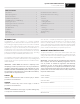
Operation & Installation Manual C-Series (HC24 models) Table of Contents Introduction........................................................................................................... 3 Warranty Registration...................................................................................... 3 General Precautions.......................................................................................... 4 Installation Specifications...................................................................
Operation & Installation Manual C-Series (HC24 models) GENERAL PRECAUTIONS DANGER Risk of child entrapment, before you throw away your old refrigerator or freezer, take off the doors and leave shelves in place so that children may not easily climb inside. DANGER Altering, cutting of the power cord, or removal of the power cord, removal of power plug, or direct wiring can cause serious injury, fire and/or loss of property and/or life and will void the warranty.
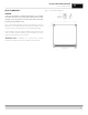
Operation & Installation Manual C-Series (HC24 models) 50" Area in which electrical outlet must be located. 9 7 16" HC24 Models CSERIES HC24 CABINET Power cord 65/8" off floor.* 1 6 4" 3 1 16" Min. 20" clearance from a corner to acheive 90 door swing. 9 7 16" Power cord 65/8" off floor.* 3 18 16" 7 23 8" 20" 18 16" * Leg leveler can add 3/4"50" toArea theseindimensions which 90° Swing required for pullout shelf clearance. 1 23when fully extended. 16" outlet electrical must be located.
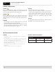
Operation & Installation Manual C-Series (HC24 models) PREPARING THE SPACE Make sure that the space where the Perlick cabinet(s) is/are to be installed is properly prepared. Refer to Figures 1 and 2 (page 5) to ensure proper space dimensions and electrical service are correct for the model to be installed. CAUTION If cabinet is being installed under a countertop it is recommended that the countertop be supported by structure other than the refrigerated cabinet to prevent damage to the counter top.
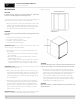
Operation & Installation Manual C-Series (HC24 models) ANTI-TIP BRACKETS Figure 5 - 24” Anti-Tip Kit Drawing WARNING Unit may tip forward if loaded racks/shelves are all pulled out at the same time. To prevent tipping and provide a stable installation, the unit must be secured in place with the anti-tip brackets provided with the unit. A set of metal anti-tip brackets and necessary hardware is supplied with the unit.
Operation & Installation Manual C-Series (HC24 models) INSTALLATION Figure 6 - Leveling CAUTION Finished flooring should be protected with the appropriate material to avoid damage from moving the unit. If unit has been laid on its back or sides, place unit upright and allow minimum of 24 hours before connecting power. 1. Plug the unit into the 15 amp grounded outlet located in the installation opening.
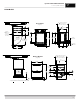
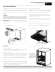
Operation & Installation Manual C-Series (HC24 models) TOE PLATE INSTALLATION When the unit is secured in place, install the louvered toe plate. Secure louvered toe plate by snapping the latch into the latch catch on the unit. Refer to Figure 7 (below) for Toe Plate Installation Illustration and Figure 8 (page 10) for Toe Plate Wood Overlay template. CAUTION The louvered toe plate must be removed to service the unit. The floor cannot interfere with removal.
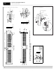
SW B B C 7/8" 7/64" 9/32" 1/4" 1/2" 1/8" 7/64" 9/32" 3/32" 1/32" THICK (20GA) GALVANIZED OR STAINLESS STEEL RECOMMENDED 2 METAL CLIP REQUIRED FOR SNAP IN RETAINER THAT ASSEMBLES GRILL TO THE UNIT. THIS CLIP MUST BE SCREWED TO THE GRILL USING THE FEATURES SHOWN IN DETAIL VIEW "D" 5/32" 43/64" 29/64" 7/32" 1" 3/32" 3/8" 11/16" 3/8" DETAIL C SCALE 1 : 2 1" DETAIL D SCALE 1 : 1 5/16" TYPICAL 3/16" TYPICAL 3" TYPICAL 1 DRAWN CHECKED FINISH: QTY.
Operation & Installation Manual C-Series (HC24 models) Drawers Drawer units (available in Refrigerator units only) come standard with two drawers. Like shelving, drawers are full-extension. To remove drawers: 1. Pull the drawer out to its farthest point. 2. Locate the tabs in the middle on both sides of the extenders. Press left tab up and right tab down; pull shelf out. 3. Move each extender separately. Hold the middle of one extender, pull the front up then move extender 1/2-inch to the inside of unit.
Operation & Installation Manual C-Series (HC24 models) Figure 13 - Solid wood overlay panel template 12
Operation & Installation Manual C-Series (HC24 models) Figure 14 - Glass wood overlay panel template 13
Operation & Installation Manual C-Series (HC24 models) Figure 15 - Wood overlay drawer panel template 14
Operation & Installation Manual C-Series (HC24 models) Figure 16 - Lock installation, solid wood overlay door panel 15
Operation & Installation Manual C-Series (HC24 models) Figure 17 - Lock installation, wood overlay glass door panel 16
Operation & Installation Manual C-Series (HC24 models) Figure 18 - Lock installation, wood overlay drawer panel 17
Operation & Installation Manual C-Series (HC24 models) Handle Installation WOODEN WINE RACK TRIM FINISHING (optional) CAUTION Handle mounting on wood overlay door should be mounted on overlay panel only (not the door) to avoid damage to the factory door. All wine racks come with sleek stainless steel fronts. Unfinished solid hardwood fronts are optional and can be removed and replaced with other wood to match your cabinetry. See Figure 19 (below) for wine rack face details.. 1.
Operation & Installation Manual C-Series (HC24 models) OPERATION CHECKING PRODUCT TEMPERATURE General All HC24 models are equipped with a state-of-the-art refrigeration system and are frost-free. The evaporator coil automatically defrosts on demand at predetermined intervals. To accurately check the temperature of product stored in the refrigerated compartment insert an accurate thermometer into a plastic (non-breakable) bottle, partially filled with water. Tighten the bottle cap securely.
Operation & Installation Manual C-Series (HC24 models) CAUTION Do not use abrasive cleaners or cloths on any of the interior or exterior surfaces or removable parts. Cleaning the Condenser The condenser should be cleaned every three (3) months. The condenser is located behind the toe plate (Figure 6, page 10). Remove the toe plate and use a soft bristle brush and vacuum to remove the dust and lint. Avoid damaging or crushing the condenser fins or tubing. Upon completion, reinstall the toe-plate.
Operation & Installation Manual C-Series (HC24 models) Problem: The refrigeration system runs for long periods of time • Is the condenser area clean and free of obstructions? • Have the doors been open for a long time or more frequent door openings occurred? • Has warm product been placed in the cabinet? • On hot days and in warm room temperatures the system will run longer Problem: Condensation forms inside the refrigerated compartments • This is normal during high humidity and frequent door openings • Are
Operation & Installation Manual C-Series (HC24 models) RESIDENTIAL PRODUCTS WARRANTY 1A. PERLICK RESIDENTIAL REFRIGERATION PRODUCTS LIMITED WARRANTY (excludes H50IM Clear Ice Makers; see warranty on page 31) ENTIRE PRODUCT - Full Three Year Warranty*: For three (3) years from date of original purchase, Perlick Corporation’s warranty covers all parts and labor to repair or replace any part of the product, which proves to be defective in material and workmanship.
This limited warranty is in lieu of any other warranty, expressed or implied, including, but not limited to any implied warranty of merchantability or fitness for a particular purpose; provided however, that to the extent required by law, implied warranties are included but do not extend beyond the duration of the express warranty first set above. Perlick’s sole liability and your exclusive remedy under this warranty are set forth in the initial paragraph above.