
Tap Installation Instructions

PERLICK RESIDENTIAL INSTALLATION MANUAL FOR BEER DISPENSING EQUIPMENT
8 | perlick.com/residential
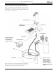
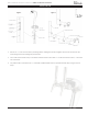
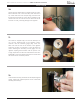
If installing a two faucet system, a CO2 manifold will need
to be installed. Locate the red CO2 lines, CO2 manifold and
a #10 x 1/2” sheet metal screw. Slide one end of each hose
onto the barbed ngs on the manifold and clamp. On the
le rear side wall of the beer compartment there is a double
row of screws which run vercally. Remove one of the two
top screws and discard. Insert the sheet metal screw through
the manifold and into the hole vacated previously.
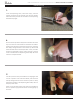
On a single beer system, locate the red CO2 hose. Slide one
end onto the barbed ng of the regulator assembly and
clamp. On systems with two beers, locate the CO2 line that
comes o the backside of the manifold assembly. Slide the
hose onto the barbed ng of the regulator assembly and
clamp. For detailed informaon on connecng the regulator
to the CO2 cylinder, see page 10.
7.
8.
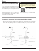
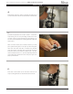
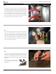
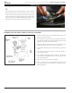
Locate the low prole keg coupler(s). Slide one of the red
CO2 lines onto the larger barbed ng of coupler and clamp.
Locate one of the black beer lines and slide onto the smaller
barbed ng of the coupler and clamp. Repeat for addional
couplers.
Note: This unit comes standard with
Perlick’s new 304SS Lo-Boy coupler
(40030SSLD)
9.
INSTALLATION