
C-Series Operation & Installation Manual


9
Operation & Installation Manual
C-Series (HC24 models)
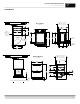
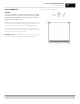
TOE PLATE INSTALLATION
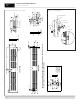
When the unit is secured in place, install the louvered toe plate.
Secure louvered toe plate by snapping the latch into the latch
catch on the unit. Refer to Figure 7 (below) for Toe Plate Installation
Illustration and Figure 8 (page 10) for Toe Plate Wood Overlay
template.
CAUTION
The louvered toe plate must be removed to service the unit. The
oor cannot interfere with removal. The louvered sections must
not be covered or obstructed to prevent proper air circulation.
IMPORTANT NOTE: To achieve maximum performance, interior
louver openings and fan guard openings should never be
obstructed.
SHELVING
Single Door Refrigerator
The single door unit comes standard with two Industry Exclusive
full-extension black vinyl-coated pullout shelves.
Single Door Wine Reserve
The single door unit comes standard with ve full extension
black vinyl coated pullout wine racks capable of storing 40 total
wine bottles. Wine shelves are removable and adjustable to
accommodate oversized (magnum) bottles. Additional storage is
available on the lower step for an additional ve wine bottles.
Single Door Beverage Center
The single door unit comes with two full-extension black vinyl-
coated wine racks and one Industry Exclusive full-extension black
vinyl-coated pullout shelf allowing for storage of both wine and
beverages. Shelving positions are adjustable.
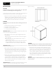
Adjusting Full-extension Shelving
1. Pull the shelf out to its farthest position. Locate the tabs in the
middle of both extenders (Figure 9, below). Lift one tab up
while pushing the opposite tab down and pull shelf out.
2. Reposition each bracket separately. Grasp the middle of
the bracket, pull the front end up and out, then forward to
remove (Figure 10, below).
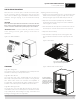
3. Place bracket at the desired position. Push the rear hook into
the rear key slot. Set front of the bracket on the wall hook.
4. Repeat for other bracket(s).
5. Push extenders completely into the unit. Align the shelf
grooves with the extenders and slide completely into the
unit.
Figure 7- Toe Plate Installation
Figure 9- Tab location
Figure 10- Bracket and extender location
Lift one tab up while pushing the
opposite tab down and pull shelf out
To remove brackets,
remove shelf, lift front
of bracket to disengage
the front key slot, and
pull forward to disengage
the rear key slot.