
Installation Instructions

PERLICK RESIDENTIAL UNDERCOUNTER INSTALLATION MANUAL
Perlick customer service (800)558-5592 | 5
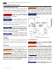
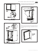
13-⁄”
⁄”
⁄”
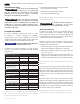
Figure 2A. 15” Anti-tip Kit
22-⁄”
⁄”
⁄”
Figure 2B. 24” Anti-tip Kit
REPAIR & MAINTENANCE
WARNING
All service work shall be performed
by Perlick-authorized service
personnel. All component parts shall be replaced with
like components. Incorrect parts or improper service
may result in re.
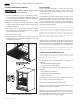
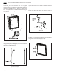
INSTALLING CASTERS OR LEGS OPTIONAL
Attach bracket assembly to the bottom of the cabinet base
using the ¼”-20 Philips head machine screws provided.
Attach casters or legs to the mounting bracket with ¼” –
20 Philips head screws provided
N OTICE
Anti-tip brackets are only used for
stationary cabinets and should not
be installed on cabinets with accessory casters. Caster
kits are available for HP, HC and HA model cabinets.
Refer to the instructions supplied with the caster kit
for proper installation.
N OTICE
If installing on a concrete oor,
concrete fasteners are required and
not included with the anti-tip kit.
N OTICE
Some installation sites may require
modications to provide a secure
surface for attaching the brackets.
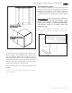
A set of anti-tip brackets is supplied with the unit. These
brackets should be attached to the oor at the rear of the
unit. Each bracket must be located to engage the rear
glides when the cabinet is pushed back into position. Refer
to Figures 2A and 2B (shown on right) for anti-tip bracket
mounting locations.