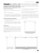
Installation Manual HP15 HP24 HP48 HH24 HC24 HA24 15” SIGNATURE SERIES 24” SIGNATURE SERIES 48” SIGNATURE SERIES SIGNATURE SERIES SOTTILE C-SERIES ADA-COMPLIANT SERIES Form No. Z2348-C Rev. 03.03.
PERLICK RESIDENTIAL INSTALLATION MANUAL TABLE OF CONTENTS Warranty Information ..................................................................2 Door Information.............................................................................8 Safety Information..........................................................................4 Changing the Door Swing Direction..................................8 Plumbing, Electrical and General Information..............4 Handle Installation......................
PERLICK RESIDENTIAL INSTALLATION MANUAL REMEDY: Perlick will provide the parts and labor necessary to repair or replace (at Perlick’s option) any parts proven to be defective in material or workmanship during the Basic Warranty Period. Perlick will provide the replacement parts, but not the labor, for any parts of the hermetically sealed refrigeration system proven to be defective in materials or workmanship during the Extended Warranty Period.
PERLICK RESIDENTIAL INSTALLATION MANUAL SAFETY PLEASE READ all instructions completely before attempting to install or operate the unit. Take particular note of the DANGER, WARNING and CAUTION information in the manual. The information is important for the safe and efficient installation, operation and care of your Perlick unit. DANGER Indicates a hazard that WILL result in serious injury or death if precautions are not followed.
PERLICK RESIDENTIAL INSTALLATION MANUAL DANGER Serious Electrocution Hazard! Electrical grounding is required. This appliance is equipped with a 3-prong (grounding) polarized plug for your protection against possible shock hazards. Failure to comply with these electrical guidelines may result in possible death or serious injury, fire, or loss of property. • Never remove the round grounding prong from the plug. • Never use a 2-prong adapter. • Never use extension cord to connect power to the unit.
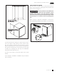
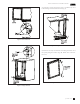
PERLICK RESIDENTIAL INSTALLATION MANUAL PREPARING THE SPACE CAUTION If the unit is to be installed under a countertop, it is recommended that the countertop be supported by a structure other than the unit itself to prevent damage to the unit. 2).
PERLICK RESIDENTIAL INSTALLATION MANUAL TOE PLATE INSTALLATION Once the unit is secured in place, install the louvered toe plate. Secure the plate by snapping the latch into the latch catch on the unit (Figure 5). CAUTION The toe plate must be removed to service the unit. The floor cannot interfere with removal, and the louvered sections must not be covered or obstructed. Obstructions could prevent proper air circulation, which may damage the unit.
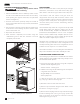
PERLICK RESIDENTIAL INSTALLATION MANUAL SHELVING/DRAWER ADJUSTMENTS CAUTION Completely empty shelf or drawer before removing. 1. Pull the shelf/drawer out to its furthest position. Locate the tabs in the middle of both extenders. Lift one tab up while pushing the opposite tab down, and pull shelf/ drawer out (Figure 6). 2. Position each bracket separately. Grasp the middle of the bracket, pull the front end up and out, then forward to remove it. 3. Place bracket at desired location.
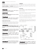
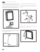
PERLICK RESIDENTIAL INSTALLATION MANUAL 5). Using the screws removed in step 3, install the top and bottom hinge brackets from the kit (Fig. 9). Figure 7. Door Removal Figure 9. Hinge Installation 6). Remove the top and bottom door hinge brackets and the push plunger brackets (Fig. 10). Retain the screws for later use. Figure 10. Door Brackets Figure 8. Hinge Removal perlick.
PERLICK RESIDENTIAL INSTALLATION MANUAL 7). Remove the front panel from the door assembly by removing the door gasket and then removing the overlay mounting screws, 4 per side, from the perimeter of the door assembly (Fig. 11). Rotate the front panel 180°. The top becomes the bottom. Reattach using the same screws and mounting holes and then reinstall the door gasket. 9). Insert the bearing into the door hinge bracket (Fig. 13). 10).
PERLICK RESIDENTIAL INSTALLATION MANUAL 12). Place the lower V-block into the lower cabinet hinge with the notch parallel to the cabinet (Fig. 15). HANDLE INSTALLATION The handle mounting on the wood CAUTION overlay should be mounted on the overlay only (not the actual door) to avoid damage to the factory door. 1. Handle must be attached to the overlay before mounting the overlay onto the door. Mark the rear of the wood overlay panel with handle fastening locations. 2.
PERLICK RESIDENTIAL INSTALLATION MANUAL WOOD OVERLAY INSTALLATION (FOR -2, -4 AND -6 MODELS) Before beginning installation, check all components for proper fit and finish. CAUTION For best performance and functionality, the overlay panels should be 3/4” thick. The weight of the overlays should not exceed 20 lbs for solid (-2) doors, 10 lbs for glass (-4) doors, or 10 lbs for drawer (-6) models. WINE RACK TRIM (OPTIONAL) All wine reserve racks come with sleek stainless steel fronts.
Use and Care Guides, Specification Sheets, Wood Overlay Templates for Doors, Drawers and Grilles, and Corresponding Compliance and Energy Guides are available for download at www.perlick.com/residential-products/service-support. Contact Perlick Customer or Technical Service at 800.558.5592. Customer Service and Technical Service are available business days Monday through Friday from 7:00 a.m. to 7:00 p.m. CST. 8300 W. Good Hope Road, Milwaukee, WI 53223 • 800.558.5592 • info@perlick.com • www.perlick.