PERMA PURE INSTRUCTION MANUAL THERMO-ELECTRIC COOLER SO3 AEROSOL REMOVAL SERIES MODEL 10410 Version 4.05 Perma Pure LLC 8 Executive Drive Toms River, NJ 08755 www.permapure.com Tel: 732-244-0010 Tel: 800-337-3762 (toll free US) Fax: 732-244-8140 Email: info@permapure.
TABLE OF CONTENTS A: Specifications................................................................................................................ 3 B: Limited Warranty........................................................................................................... 4 C: Principle of Operation ................................................................................................... 5 D: Installation .........................................................................................
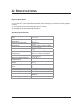
A: SPECIFICATIONS Physical Description 2 x 10” Durinert® (inert coated stainless steel) heat exchangers connected in series (passive / active) 2 x 10” packed Kynar heat exchangers (active / active) 3 LCD displays w/ associated LED indicators Operating Specifications Standard Sample Gas Flow Rate Maximum Inlet Dew Point at Rated Flow Maximum Cooling Rate 5-10 LPM 10.6-21 SCFH 173qF @ 43% H2O 78qC 898 BTU/Hr 952 kJ/Hr Dimensions 14.55 x 12.62 x 12.32 in. HWD 37.0 x 32.1 x 29.
B: LIMITED WARRANTY Perma Pure LLC WARRANTY and DISCLAIMERS Perma Pure (Seller) warrants that product supplied hereunder shall, at the time of delivery to Buyer, conform to the published specifications of Seller and be free from defects in material and workmanship under normal use and service.
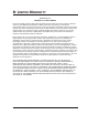
C: PRINCIPLE OF OPERATION Thank you for purchasing a Baldwin™ Model 10410 SO3 Aerosol Removal Series Thermo-Electric Cooler. Perma Pure’s Baldwin SO3 Aerosol Removal Series Thermo-Electric Coolers are specifically designed to remove SO3 and condensate from sample streams in high ambient temperature & high water volume applications. Each model in our SO3 Aerosol Removal Series feature an oversized heat sink and high performance thermoelectric devices for high heat removal capacity.
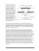
as a small heat pump with no moving parts. The Peltiers operate on direct current and may be used for heating or cooling by reversing the direction of current flow. This is achieved by moving heat from one side of the module to the other with current flow and the laws of thermodynamics. A typical single stage Peltier (figure 1) consists of two ceramic plates with p- and ntype semiconductor material (bismuth telluride) between the plates.
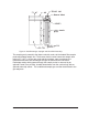
Figure 2: Heat Exchanger, Impinger and Heat Sink Assembly The sample gas is passed to the thermo-electric cooler via the heated filter sample probe and heated sample line. The thermo-electric cooler lowers the sample dew point to 5°C (41°F). As the gas cools and the moisture vapor condenses, the condensate exits the heat exchanger through the bottom drain connection.
D: INSTALLATION The Model 10410 thermoelectric sample cooler should be installed away from heat sources in a well ventilated area of an instrument rack or enclosure. Sample tubing connections to the Model 10410 depend on the heat exchanger material of construction. A stainless steel fitting is used on the first heat exchanger (sample line inlet) if the heat exchanger is stainless steel or Durinert® coated stainless steel, otherwise a Kynar® fitting is used.
E: START-UP PROCEDURE Plug in the power cord to a properly grounded main circuit. The Ready Green LED will come on within 3 minutes, indicating the ready temperature (10°C) has been achieved on Channel 1 and the gas sample flow can begin. After approximately 3 minutes, the set point of +5°C (41°F) will be achieved. The SLIP Green LED is always on unless, (1) moisture is detected by the water slip sensor (optional upgrade), (2) the cooler was ordered without a relay board, or (3) there is a malfunction (e.g.
F: LED SUMMARY The Model 10410 has 3 LCD temperature displays and three LED status displays for each active channel (2 green, 1 red per channel). Channel 1 is a standard active channel (4°C). Channels 2 and 3 alternate on a freeze / thaw cycle between -7°C and ambient. The “Ready” Green LED’s come on when the relay set point temperature is reached for each channel.
G: RELAY BOARD The water slip alarm option is a secondary board that is mounted on the main control board. This board has two inputs and three outputs per channel. The first input, which comes from the main control board, is the ready input. The second input, which comes from the water slip sensor, is the water slip input. The first output, which is fed back to the main control board, controls the ready and water slip LED(s). The second output is a 1/4 amp SPST form A dry contact relay.
H: TROUBLESHOOTING If the front panel LCD digital indicators fail to show proper operating temperatures for all controlled heat exchangers as described above, refer to the following troubleshooting procedures: The first problem to check is cooler overload. Check the incoming sample gas temperature, moisture content, and flow rate through the heat exchanger to be sure all conditions are within our published specifications. Overload requires more cooling power from the Model 10410 than is available.
Symptom No LED(s) and no fan. Check AC power input. No LED(s) and both fans on. AC input fuse (2A) on control board. DC output fuse (1A) on control board. VCC on control board. (+5VDC and –5VDC). AC input fuse (15A) on power supply. +13.5VDC at P13 and P14 on control board. If Peltier elements are cooling the heat exchangers. Voltage at P13 & P14 Should be at +13.5VDC Peltier current draw. Should be above 6 amps. LED(s) on and no power supply fan. Impinger remains at ambient temperature.
For further service assistance, contact: Perma Pure LLC 8 Executive Drive Toms River, NJ 08755 Tel: 800-337-3762 (toll free U.S.) Tel: 732-244-0010 Fax: 732-244-8140 Email: info@permapure.
I: SPARE PARTS Model 10410 Part No. Description 3CCB-009E* Control Board, Model 545 & 10410 2FAN-005 Fan: 12 120 VDCVAC Fan: Muffin, Muffin, 4” 4” xx 1”, 1 ½”, 2FAN-010 2FAN-007 Fan: Muffin, 6” x 1 ½”, 12 120VDC VAC 3CXD-003 Heat Exchanger: 10” Durinert® 3CXD-022 3CXG-006 Heat Exchanger: 10” Glass 3CXK-005 Heat Exchanger: 10” Kynar, Aerosol-packed 3KPE-004* Peltier Element Kit, 40 mm 1PSD-010* Power Supply: 500W, 600W, 13.
APPENDIX A: MODEL 10410 16
A B C D C54 VCC 100uf OS-CON VCC VCC 2 1 14 3 15 6 7 3.3K R43 3.3K R42 OINH IN1 MONO 1 10K R37 10K R36 MC14536B R S + .1uf C40 VCC DOUT OUT2 OUT1 20 19 18 17 16 15 14 13 12 11 + TP10 68uf C59 100uH .1uf 8 7 6 5 D3 SA5.0 +V OSC LV Vout C41 L1 SW-DIP10 SW1 68uf C58 MAX660 NC +CAP GND -CAP 8BYP CLKINH A B C D U14 1 2 3 4 5 6 7 8 9 10 1 amp F2 9 10 11 12 VCC + 1 2 3 4 1 13 5 C55 9 10 11 6 7 1 2 3 14 15 TP11 TIMER_OUT .1uf .1uf C34 .
1 2 3 4 VCC CHANEL 1 R12 1M F F Q3 2N3904 R9 100K U3 1 VCC 38 C3 47pf R6 39 40 549K C8 R24 34 .47uf 33 200K R15 VEE 20K 4 R23 TEMP_1 200K .47uf R3 28 1.5M U9A 2 29 C9 1 3 R22 200K LM358A U9B 6 C12 27 .
1 2 3 4 R4 RN1B 3 4 VCC .1UF VCC 5 C25 8 6 1M TEMP_1 F 7 3 .001uf LM311 C61 + TP1 FOR ZERO AND SPAN ADJ. R13 4.7K 3 C2 VEE 14 13 12 11 10 9 8 +IN -IN +C -ALM +T +ALM COM V+ -T COMP -C Vo VFB 1 A4 A3 A2 A1 Y4 Y3 Y2 Y1 12 14 16 18 CHN1_READY_LED CHN1_READY TC_1_OK G MC74HC240A TC_1_LED R5 20K 1M POT3 VEE VCC VCC C62 VCC VCC .1uf READY TEMP. 8 100 R10 1 2 3 4 5 6 7 VEE 2 1 TC1_SENSE U9 1 TC1_SENSE .1uf 1 2 YEL .1uf TP2 TP1 TB1 RED .
Bob MacRae Digitally signed by Bob MacRae DN: cn=Bob MacRae, o=Perma Pure, ou=Engineering, email=bmacrae@permapure.com, c=US Date: 2008.11.
APPENDIX B: SAMPLE CONDITIONING SYSTEM 17
Digitally signed by Bob MacRae DN: cn=Bob MacRae, o=Perma Pure, ou=Engineering, email=bmacrae@permapure.com, c=US Date: 2011.05.
AIR DIMENSIONS INCORPORATED 1371 West Newport Center Dr., Suite 101, Deerfield Beach, FL 33442 - Phone 954-428-7333 or 800-423-6464 Fax 954-360-0987 http://www.airdimensions.com e-mail address -Info@AirDimensions.com MINI DIA-VAC® MAINTENANCE AND DISASSEMBLY INSTRUCTIONS A. General Operations Characteristics 1. Normal motor coil temperatures may be 160 - 180 degrees F. Winding insulation is Class B. Please note the two fans are different, so before removing the fans, note which side they belong on. 2.
*Diaphragms require close precision tolerance, therefore only ADI diaphragms should be used as replacements. C. Disassembly of Head Section and Service Diaphragm 1. Remove head section by unscrewing the four large bolts. A flat-bladed screw driver may be needed to gently pry the head free of the service diaphragm. **If you have Teflon coating on the heads use caution not to scratch the surface. 2.
E. Related Torque Values 1. Head bolts - 110 inch pounds. 2. Valve body screws and Diaphragm plate screws - 70 inch pounds Dia-Vac® is a Registered Trademark of Air Dimensions Inc.
1. Single Pump Head Loading Note: Use only MASTERFLEX Precision Tubing with MASTERFLEX Pumps to insure optimum performance. Use of other tubing may void applicable warranties. Contents: One pump head, one 15 in (38 cm) length of silicone tubing, one mounting hardware package, manual and tubing loading key. Supplied tubing loading key required for assembly. a) Separate the end bells (the pump head halves). Hold the end bell containing the rotor as shown with the tubing retainer grooves facing down.
Set contains four #8-32 screws, four washers, and four wingnuts. Number of heads To be mounted 1 2 3 4 Cold- rolled steel Order number MN-07013-02 MN-07013-03 MN-07013-03 MN-07013-07 Stainless steel Order number MN-07013-04 MN-07013-05 MN-07013-08 MN-07013-09 2. Multi-Channel Mounting Flat bladed screwdriver required for mounting. Tubing loading key required for mounting. Note: Other special mounting hardware for multi-channel pumping. See “ 3. Replacement Parts and Accessories”.
CHART OF VOLUME PERCENT WATER CONCENTRATIONS AT SATURATION FOR VARIOUS TEMPERATURES AT STANDARD PRESSURE (ATMOSPHERIC PRESSURE) DEGREES C DEGREES F VOLUME % DEGREES C DEGREES F VOLUME % +100 + 212 100.00 +2 + 36 0.696 + 90 + 194 69.20 +1 + 34 0.649 + 80 + 176 46.70 0 + 32 0.602 + 75 + 167 38.70 -1 + 30 0.555 + 70 + 158 30.70 -2 + 28 0.510 + 65 + 149 25.20 -3 + 27 0.469 + 60 + 140 19.70 -4 + 25 0.431 + 55 + 131 15.50 -5 + 23 0.396 + 50 + 122 12.20 -6 + 21 0.363 + 45 + 113 9.45 -7 + 19 0.333 + 40 + 104 7.
MOISTURE CONVERSION TABLE DEWPOINT F C -110 -108 -106 -104 -102 -100 -98 -96 -94 -92 -90 -88 -86 -84 -82 -80 -78 -76 -74 -72 -70 -68 -66 -64 -62 -60 -58 -56 -54 -52 -50 -48 -46 -44 -42 -40 -38 -36 -34 -32 -30 -28 -26 -24 -22 -20 -18 -16 -14 -12 -10 -8 -6 -4 -2 0 +2 +4 +6 +8 +10 +12 +14 +16 +18 +20 +22 +24 +26 +28 -166 -162 -159 -155 -152 -148 -144 -141 -137 -134 -130 -126 -123 -119 -116 -112 -108 -105 -101 -98 -94 -90 -87 -83 -80 -76 -72 -69 -65 -62 -58 -54 -51 -47 -44 -40 -36 -33 -29 -26 -22 -18 -15 -1