eCOOL™ 5000XP Series Digital Thermo-Electric Cooler Instruction Manual PERMA PURE Tel: 732-244-0010 Tel: 800-337-3762(toll free US) Fax: 732-244-8140 Email: info@permapure.com Web: www.permapure.com Version 5.
TABLE OF CONTENTS A: SPECIFICATIONS .......................................................................................................... 3 B: LIMITED WARRANTY .................................................................................................... 4 C: PRINCIPLE OF OPERATION ......................................................................................... 5 D: INSTALLATION ..............................................................................................................
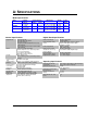
A: SPECIFICATIONS Model Specifications Model e5500XP e5800XP e5900XP Standard Capacity 4-7 LPM 8-15 SCFH 7-10 LPM 15-21 SCFH 10-20 LPM 21-42 SCFH Heat Exchangers Passive Active 1x10 in. 1x10 in. 2x10 in. 2x10 in. 2x10 in. General Specifications Digital Boards Alarms Display Heat Exchanger Type Heat Exchanger Material Heat Exchanger Connections Heat Sink Voltage Sample Pump (Optional) Drain Pump (Optional) Dimensions Weight 14 x 13 x 13 in. HWD 36 x 33 x 33 cm HWD 14 x 13 x 13 in.
B: LIMITED WARRANTY Perma Pure LLC WARRANTY and DISCLAIMERS Perma Pure (Seller) warrants that product supplied hereunder shall, at the time of delivery to Buyer, conform to the published specifications of Seller and be free from defects in material and workmanship under normal use and service.
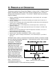
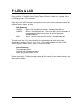
C: PRINCIPLE OF OPERATION Thank you for purchasing a Perma Pure Baldwin™-Series eCOOL™ 5000XP Series Digital Thermo-Electric Cooler CSA-C and CSA-US certified for Class I Division 2 Groups A,B,C,D hazardous locations. The eCOOL™ 5000XP Series has numerous features including: Remote monitoring and control of heated filter probe, heated sample line, and sample conditioning system. eCOOL™ interface software included for monitoring and control over the Internet or a Local Area Network.
When a positive DC voltage is applied to the n-type thermo-electric element, electrons pass from the p- to the n-type thermo-electric element and the cold side temperature will decrease as heat is absorbed. The heat absorption (cooling) is proportional to the current and the number of thermo-electric couples. This heat is transferred to the hot side of the Peltier element where it is dissipated into the heat sink and surrounding environment.
The sample gas is passed to the thermo-electric cooler via the heated filter sample probe and heated sample line. The thermo-electric cooler lowers the sample dew point to 5°C (41°F). As the gas cools and the moisture vapor condenses, the condensate exits the heat exchanger through the bottom drain connection. Particulate matter which passes through the sample cooler is removed by an optional Perma Pure pre-filter, located downstream from the cooler along with an optional water slip sensor.
D: INSTALLATION WARNING! eCOOL™ 5000XP Digital Thermo-Electric Coolers and related components must be installed with appropriate conduit and connections for area classification subject to the local inspection authority having jurisdiction. eCOOL™ 5000XP Digital Thermo-Electric Coolers should be installed away from heat sources in a well ventilated area of an instrument rack or enclosure. Sample tubing connections to the eCOOL™ 5000XP Coolers depend on the heat exchanger material of construction.
E: START-UP PROCEDURE WARNING! eCOOL™ 5000XP Digital Thermo-Electric Coolers and related components must be installed with appropriate conduit for power cords and connections for area classification subject to the local inspection authority having jurisdiction. Plug in the power cord to a properly grounded main circuit. The LCD should display the actual temperature. The temperature of each channel should fall until it reaches 5C.
F: LEDS & LCD Every eCOOL™ 5000XP Series Digital Thermo-Electric Cooler has a jumbo 2-line LCD display and 2 LED indicators. Each of the two LED indicators corresponds to an active heat exchanger and will be colored Green, Amber, or Red: LED Summary GREEN: Status OK, Sampling can begin. Sample pump will run. AMBER: Alarm is no longer present. User must press the reset button to acknowledge the alarm and return to normal operation. Sample pump off. RED: Alarm - see message on LCD screen. Sample pump off.
G: BOARDS Control Board The control board is the motherboard for the eCOOL system. The control board handles the majority of the functions for the cooler module. It contains the micro processor that controls all of the functional areas of the design, as well as the temperature measurement of the controlled vapor flow as well as the Pulse Width Modulation (PWM) control of the Peltier elements to cool the vapor.
high current draw, and reconnect power. It could take up to 5 minutes for a fuse to self-reset in a power off state. Main Control Board Overview Configuration Switches The configuration switches identify which components are connected to the system. They are used by the control firmware to determine how the board is going to operate in the system. The switches are read at power-up, or when the external reset switch is activated. The table below identifies the switch positions and their functions.
SW3 Function OFF ON 1 Heated Line Control OFF ON 2 Probe Control OFF ON 3 Peltiers 1 per channel 2 per channel 4 Channels 1 2 5 Peltier Power Share Full Power Power Sharing 6 ISO Channels Inactive Displayed SW2 Function ON OFF 1 ICE VCC Enabled Disabled 2 JTAG ICE ResetN Enabled Disabled 3 Calibration Enabled Normal Operation 4 Dflash Res Enabled Normal Operation 5 Init Clr Enabled Normal Operation Button Control The buttons are used to control the calibr
ChX:RDY TMP= xxC ChX:SET TMP= xxC ChX GAIN=%3u Probe, Heated Line Min = 0°C Span = Max = 360°C Calibration is performed by setting the gain of the span circuit to minimal gain then adjusting the 0 point to the minimum reading from the ADCC. The span temperature is used to measure the ADCC value and calculate the step size of the ADCC.
B: Sample Pump Control – Water slip, over-temperature, thermocouple failure alarms. Wire the Line (hot) power for the sample pump through terminals through JP3 and JP1. Wire the Common and Normally Open (NO) contacts in series. If an alarm occurs, one or both of these contacts will open. The sample pump is now in series with the Water Slip (Moisture Carryover) Sensor and the Ready/Slip/power failure relay, which will only allow the sample pump to start if conditions are satisfactory (i.e.
H: DEFAULT SETPOINTS eCOOL™ 5000XP Heat Exchangers: Setpoint Temperature = 5°C Run Temperature = 10°C Cooler must operate below the Run Temperature to avoid the over temperature alarm condition. Heated Sample Probe: Setpoint Temperature = 190°C High Temperature Alarm = 210°C Low Temperature Alarm = 120°C Heated Sample Line: Setpoint Temperature = 190°C High Temperature Alarm = 210°C Low Temperature Alarm = 120°C LAN Card: Static IP Addressing: 192.168.45.140 DHCP Disabled.
I: “NEW JERSEY” THERMOCOUPLE OPTION Some air quality management districts (e.g., those in New Jersey and Southern California) require temperature measurement of the gas stream at the outlet of the last heat exchanger on the cooler. Perma Pure offers a 1/32-inch diameter hypodermic-style type K thermocouple that can be inserted into a special heat exchanger (i.e., it has a small port for insertion of the thermocouple) so the actual sample dew point temperature can be measured.
J: MAINTENANCE Note: Please refer to the Spare Parts section of this manual for part numbers and descriptions. Daily Verify each channel is running at 5°C (+/- 1.5°C). LED’s should be Green. Verify cooling fans are running. Verify that the peristaltic pump is running and water is draining out. Verify that the sample pump is drawing full flow. Quarterly Verify power supply voltage is above 14.5 VDC. Inspect and clean the EZ-Clean Twist-Apart heat exchangers with de-ionized water.
K: TROUBLESHOOTING Alarm Message Thermocouple Failure Channel # Symptom Thermocouple is failing or disconnected Water Slip Alarm Water has slipped passed the thermo-electric cooler and tripped the water slip sensor. Overtemp Alarm Probe Overtemp Alarm Probe Undertemp Alarm Heated Line Overtemp Alarm Heated Line Undertemp Alarm Action(s) Ensure proper connection to TB6 for Channel 1, TB7 for Channel 2. Replace K-type thermocouple.
Problem No LCD or LED(s) and no fan. Heat exchanger remains at ambient temperature. Heat exchanger frozen and cooler indicates ambient temperature. Impinger does not reach set temperature, but is below ready temperature. Heat exchanger temperature cycles up and down. Water carryover in system. Pump does not start. LCD(s) are green. Check Action(s) AC power input. Ensure that AC power is connected. DC 3A fuse (F1) on control board. Replace fuse as necessary. AC 15A fuse on power supply.
L: SPARE PARTS: eCOOL™ 5000XP Model e5500XP Part No.
APPENDIX: eCOOL™ 5000XP E Cool LAN Card Setup and Configuration Setup: 1. Start a Hyperterminal session or similar terminal emulation software and configure it to operate at 57600,8 data bits, No Parity, and 1 Stop Bit. 2. Disconnect power from the E Cool cooler card 3. Connect the E Cool LAN card that is to be configured with the following connectors: a. JP15 - 10 pin connector to DB9 adapter to serial cable connected to PC. b. JP16 - 10 pin ribbon cable to JP15 on the E Cool cooler board c.