
Owner manual


Section G: Boards 13
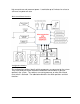
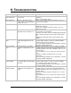
SW3
Function
OFF
ON
1
Heated Line Control
OFF
ON
2
Probe Control
OFF
ON
3
Peltiers
1 per channel
2 per channel
4
Channels
1
2
5
Peltier Power Share
Full Power
Power Sharing
6
ISO Channels
Inactive
Displayed
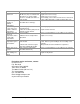
SW2
Function
ON
OFF
1
ICE VCC
Enabled
Disabled
2
JTAG ICE ResetN
Enabled
Disabled
3
Calibration
Enabled
Normal Operation
4
Dflash Res
Enabled
Normal Operation
5
Init Clr
Enabled
Normal Operation
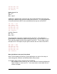
Button Control
The buttons are used to control the calibration settings. Follow the bottom line on
the display to determine the functions in the different modes. The three
combinations that are available are left only, right only, or both. To select the center
option on the bottom line of the display, press both buttons together.
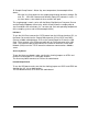
Calibration Menus
The calibration mode allows the board to be setup with min and span points as well
as all of the other configuration information applicable depending on the
configuration switch settings.
Ch1, Ch2, TC1, TC2
Min = 0
Span = 5 degrees C
Max = 8*Span Temp (360°C limit)
The calibration is performed by first calculating the expected settings for the
calibration resistors before entering the calibration operation to get a good starting
point. Then the 0 point is adjusted to the minimum point in the ADCC (memory
chip). The span temperature is then set and the span gain is adjusted to make the
span point 1/8 of the entire range for the temperature measurements.
ChX: MIN = xxC
ChX: SPAN = xxC