TABLE OF CONTENTS INSTRUCTION MANUAL Perma Pure LLC Integrator Series Model iCOOL Table of Contents 1
TABLE OF CONTENTS A: Specifications ................................................................................................................. 3 B: Limited Warranty ............................................................................................................ 4 C: Principle of Operation ..................................................................................................... 5 D: Installation ...................................................................................
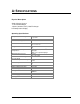
A: SPECIFICATIONS Physical Description Single Channel System 1 x 5” Heat Exchanger 1 Active (cooled to 3.5C) Heat Exchanger LCD temperature display Operating Specifications Sample Gas Flow Range 1-3 LPM 2.1-6.4 SCFH Inlet Dew Point at Rated Flow Maximum Cooling Rate 300F @ 12% H2O, 2.5 LPM 58 BTU/Hr Dimensions 7.25 x 8.25 x 10.5 in. HWD 18.5 x 21 x 26.
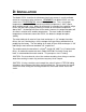
B: LIMITED WARRANTY Perma Pure LLC WARRANTY and DISCLAIMERS Perma Pure (Seller) warrants that product supplied hereunder shall, at the time of delivery to Buyer, conform to the published specifications of Seller and be free from defects in material and workmanship under normal use and service.
C: PRINCIPLE OF OPERATION Thank you for purchasing the Perma Pure Integrator Series Thermo-Electric Cooler. Our ICOOL features a unique slim design leaving additional space to install or access other sample conditioning system components. A unique shell design on this model provides easy access to electronic board, fan and the power supply. All electronic boards (control, relay, and display) are mounted on the front panel for easy access.
proportional to the current and the number of thermo-electric couples. This heat is transferred to the hot side of the Peltier element where it is dissipated into the heat sink and surrounding environment. The Integrator Series Thermo-Electric Coolers remove the moisture from the sample gas by cooling the gas as it passes through a laminar impinger (heat exchanger). A diagram showing the gas flow path through an impinger is shown in the Appendix.
lowers the sample dew point below 4o C (39.2°F). As the gas cools and the moisture vapor condenses, the condensate exits the heat exchanger through the bottom drain connection. Particulate matter which passes through the sample cooler is removed by an optional pre-filter, located downstream from the cooler along with an optional water slip sensor. The conditioned sample gas can then be directed to the gas analyzers.
D: INSTALLATION The Model ICOOL should be installed away from heat sources in a well ventilated area of an instrument rack or enclosure. REMEMBER, the Model ICOOL can only control to 61°F DIFFERENTIAL from ambient temperature. Thus, at an output temperature control of 39°F, the maximum ambient temperature is 100°F, above which cooling control is lost. When this differential is exceeded, the controller will go full-on, with the cooling capacity floating in relation to the ambient temperature above 104°F.
E: START-UP PROCEDURE Plug in the power cord to a properly grounded main circuit. The Ready Green LED will come on within 3 minutes, indicating the relay temperature (10°C) has been achieved. After approximately 3 minutes, the set point of +3.5°C. (38.3°F) is achieved. The sample gas flow may be started immediately after the Green LED comes on. The ICOOL is virtually maintenance free. However, in the event of electrical problems, contact the Perma Pure LLC service department for troubleshooting assistance.
F: LED INDICATORS The ICOOL has one green and one red LED operating indicators. These indicators are arranged horizontally on the front of the cooler. The green LED indicates the READY operating temperature status, normally set for 3.5°C (38°F). After the setpoint temperature is reached, the sample pump may be turned on by the internal relay. When the impinger temperature is below 10°C (50°F) the ready LED will be on. At one degree above the set temperature, the ready LED will be off.
G: I/O TERMINAL BLOCK DESCRIPTION The I/O terminal blocks are found on the bottom back of the cooler: TEMP OUT TEMP OUT is located between the power connector and the relay out connector. TEMP OUT is the standard analog output (low voltage DC output) for Integrator Series Thermo-Electric Coolers. ICOOL has one active 5” heat exchanger. The output is 0vdc to 5vdc for a temperature range of 0 °C to 20°C. From left to right Terminal 1 is the signal return. Terminal 2 is earth ground.
H: TEST & ADJUSTMENT PROCEDURES NOTE: All test and adjustment procedures have been performed at the factory. Therefore, no adjustment should be necessary. Remove top cover panel to access the 4 push buttons, located on the control board. The button located farthest to the right is considered Button #1 in this manual. The buttons are then numbered from right to left which the left most button being Button #4.
Ready Set Point The ready set point is the temperature the unit will turn on the output relay. The relay will be reset, turn off, at one degree above the ready set point. Press and hold Button #2 to display the ready set point. Press and hold Button #3 to increase the set point. Press and hold Button #4 to decrease the set point. The value is automatically stored when Button #2 is released. Voltage Output The voltage output can be calibrated through the push buttons.
For further service assistance, contact: Perma Pure LLC 8 Executive Drive Toms River, NJ 08755 Tel: 800-337-3762 (toll free U.S.) Tel: 732-244-0010 Fax: 732-244-8140 Email: info@permapure.