
Instruction Manual
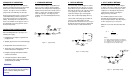


Figure 1 - Typical Setup
2. REFLUX METHOD
The reflux setup, shown in Figure 2, returns
dry sample back to the dryer for use as the
purge after it has gone through the analyzer.
Since this method uses all of the dry sample
as the purge gas, only the sample flow
required for analysis passes through the
dryer. This results in high drying efficiency.
The vacuum on the purge gas should be at
least 15” of Hg, with a higher vacuum
preferable. This vacuum level is necessary to
provide the desired 2:1 purge-to-sample flow
ratio based on the actual volumetric flow.
Figure 2 - Reflux Setup
The split sample method, shown in Figure
3, diverts some of the sample from the main
stream to be used as the purge gas. More
sample passes through the dryer than is
required for the analysis, lowering the
drying efficiency somewhat.
The following equation can be used to
determine the purge flow rate required for
the split sample method. Any units may be
used as long as they are consistent.
NOTE: Pressure units must be in absolute
terms.
V
p
= V
s
(P
s
/2P
v
) - 1
Where:
Vp = Purge flowrate (indicated on flowmeter)
Vs = Sample flowrate (indicated on flowmeter)
Ps = Sample pressure (in absolute units)
Pv = Purge pressure (in absolute units)
Figure 3 - Split Sample Setup
INSTALLATION SPECIFICATIONS
1. STANDARD METHOD 3. SPLIT SAMPLE METHODPRINCIPLE OF OPERATION
MD™-Series gas dryers are shell and tube
moisture exchangers that transfer water vapor
between two countercurrent flowing gas
streams. The dryers consist of a Nafion
®
polymer tube surrounded by an outer tube.
Dry purge gas flowing over the exterior surface
of the Nafion tubing continuously extracts
water vapor from the gas stream inside the
tubing. The driving force is the difference in
water concentration on the opposite sides of
the tubing wall. The purge gas then carries
the water vapor away.
The most efficient way to set up MD-Series
dryers is to have sample enter through the
Nafion tube (wet sample inlet) and purge gas
flowing countercurrent to the sample (refer to
Figure 1). Purge gas should be instrument
air or other dry gas. If no dry purge air is
available, one of the following methods may
be used.
When installing MD-Series gas dryers, the
following rules apply:
1. Sample pressure equal to or greater than
purge pressure
2. Sample gas pressure not to exceed 80 psig
3. Temperatures must not exceed 120°C
4. Purge air of -40°C dew point at a flow rate
of two to three times sample flow
5. Sample and purge air must flow counter-
current to each other
6. If sample dew point is above ambient
temperature, inlet of dryer must be heated
(contact factory for details)
Adjusting end fittings without following the
steps on the back page will cause twisting
of the membrane tubing and void the
warranty.
WARNING!
EXHAUST
VACUUM PUMP
NEEDLE
VALVE
VACUUM GAUGE
GAS
ANALYZER
FLOW
METER
DRY
SAMPLE
OUTLET
WET
SAMPLE
INLET
MD DRYER
EXHAUST
VACUUM PUMP
VACUUM GAUGE
GAS
ANALYZER
DRY
SAMPLE
OUTLET
WET
SAMPLE
INLET
PUMP
(OPTIONAL)
(OPTIONAL)
PURGE
AIR
FLOW
METER
NEEDLE
VALVE
SAMPLE
FLOW
METER
NEEDLE
VALVE
PRESSURE
GAUGE
EXHAUST
MD DRYER
NEEDLE
VALVE
GAS
ANALYZER
MD DRYER
FLOW
METER
DRY
SAMPLE
OUTLET
WET
SAMPLE
INLET
INSTRUMENT
AIR
INLET
DRY
SAMPLE
EXHAUST
PURGE
EXHAUST
PRESSURE
REGULATOR