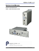
INSTRUCTION MANUAL Perma Pure LLC Integrator Series SERIES – SAMPLE GAS DRYING SYSTEM V7/11 1
Table of Contents 2
Table of Contents A: Specifications.............................................................................................................. 5 Physical Description ......................................................................................................... 5 Operating Specifications ................................................................................................... 5 B: Limited Warranty ........................................................................................
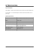
Section A: Specifications 4
A: SPECIFICATIONS Physical Description AG-412 Model – Vertically surface mounted system in aluminum case with removable cover. AG-193U Model – 19” rack mounted system in aluminum case with removable cover. 3U panel height. Operating Specifications Sample Gas Flow Range Sample gas humidity inlet Dimensions 0.5-1.
Section B: Warranty 6
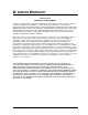
B: LIMITED WARRANTY Perma Pure LLC WARRANTY and DISCLAIMERS Perma Pure (Seller) warrants that product supplied hereunder shall, at the time of delivery to Buyer, conform to the published specifications of Seller and be free from defects in material and workmanship under normal use and service.
Section C: Principle of Operation 8
C: PRINCIPLE OF OPERATION The AG-412/193U system is a passive system in the sense that it will not move the sample gas from point A to point B. It will only dry sample gas that is pushed or pulled through it by an external pump or pressure/vacuum source. The pump in the system is present only to provide a vacuum source on the purged side of the membrane dryer. As sample gas is drawn or pushed through the system by the external pump or pressure/vacuum source, it is dried to a low moisture condition.
Section C: Principle of Operation 10
D: INSTALLATION Mounting Mount AG-412 on a vertical surface using fasteners appropriate for the surface on which it is to be mounted or install AG-193U in a standard 19” rack cabinet.
The suggested typical System connection method is shown below. Figure 3 - Typical Connection Diagram Tubing Connections Connect the sample inlet port to sample line from the sample pump. Connect the sample gas outlet to the analyzer via a tee fitting that allows excess sample flow to be vented. If required, due to sample gas composition, connect pump (purge) exhaust port to a tube that allows the system to vent in a suitable location. This is very important if the sample gas is toxic or corrosive.
E: START-UP PROCEDURE Be sure the analyzer is off and that no sample gas is being drawn through the analyzer. After confirming that the system has been properly installed, turn on the main power switch at the power inlet module. Turn the system on with the front panel power switch. The pump will start and the vacuum level will remain higher than 15”Hg when the system is operating properly.
F: DRAWINGS Section F: Drawings 14
Section F: Drawings 15
Section F: Drawings AG-412-05-01: Plumbing Diagram for MDSS Series 16
Section F: Drawings 17
Section F: Drawings AG-412-04-01: Electrical drawing for MDSS Series 18
Section F: Drawings 19
Section F: Drawings AG-412-03-01: Wall mounted MD Split Sample conditioning system 20
Section F: Drawings 21
Section F: Drawings AG-193U-03-01: Rack mounted MD Split Sample conditioning system 22
H: TEST & ADJUSTMENT PROCEDURES NOTE: All test and adjustment procedures have been performed at the factory. For further service assistance, contact: Perma Pure LLC 8 Executive Drive Toms River, NJ 08755 Tel: 800-337-3762 (toll free U.S.) Tel: 732-244-0010 Fax: 732-244-8140 Email: info@permapure.