
User Manual
Board Configuration
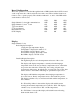
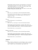
The board operation is controlled through the bank of DIP Switches labeled SW1 located
on the component side of the board in the lower left corner. These switches must be set
for the cooler to operate properly. The switches numbered 1, 2, and 3 of the DIP switch
set the function of the board.
SW 1 SW2 SW3
Single Channel Cooler with communications OFF OFF OFF
Single Channel Cooler 2
nd
board ON OFF OFF
1
st
Frozen channel OFF OFF ON
2
nd
Frozen channel ON OFF ON
Dual Channel Cooler OFF ON OFF
NJ TC Display ON ON OFF
Display
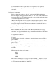
Single Channel Cooler
Basic Display Description
3 digit plus sign temperature display
Temperature is displayed in tenths of °C
Green LED to display ‘Ready’ status
Green LED to display ‘Water Slip’ status
Red LED to display ‘TC Fail’ status
Detailed Display Description
The digital display shows both temperature and status of the cooler.
The display will display temperature constantly when the impinger
temperature is below the user set ‘Ready’ temperature and no other faults
are present. One fault is the ‘Water Slip’, the sensing of liquid water
downstream of the sensor, though the use of a water slip sensor. The other
fault would be a ‘TC Failure’ indicating an open thermocouple sensor.
The display will blink the temperature when impinger temperature is
above the user set ‘Ready’ temperature and no other faults are present.
The display switches every second between blank and the temperature, in
this condition.
If a ‘Water Slip’ failure is detected the display will switch between
showing the measured temperature and a symbolic “SLP”. The display
switches every second between “WS” and the temperature.
If a ‘TC Failure’ is detected the display will switch between showing
blank and the letters “tcF”.