Prisma CD1 Compact Disc Player Owners Manual
Perreaux Industries Limited makes no warranty for the use of its products, other than those expressly contained in the warranty detailed herein. The Company assumes no responsibility for any errors which may appear in this document, reserves the right to change products or specifications detailed herein at any time without notice, and does not make any commitment to update the information contained herein.
i Introducing the Perreaux CD1 Compact Disc Player Congratulations on your Perreaux CD1 purchase. To realise the full potential of your unit you need to appreciate all aspects of its operation. Before installing the CD1 into your system, read the entire manual carefully. Endeavour to understand every detail by familiarising yourself with the controls and features as you read. You will find it easier to install using the relevant sections of this manual as a reference.
ii Important Safety Instructions Note: All safety and operation instructions should be read carefully before the CD1 is operated. Keep the Owners Manual in a safe place for future reference. The CD1 should not be used near water, for example near a bathtub, kitchen sink, in a wet basement, near a swimming pool, etc. The CD1 should be rack mounted only in a heavy-duty rack or stand that is recommended for audio equipment use.
iii Table of Contents i ii iii 1 2 3 4 5 6 7 8 9 10 11 12 13 14 15 Introducing the Perreaux CD1 Compact Disc Player ...............................................3 Important Safety Instructions ........................................................................................4 Table of Contents ..............................................................................................................5 Unpacking and Placement.......................................................................
1 Unpacking and Placement The CD1 is packaged for maximum protection. Please carefully read the instructions below before proceeding to unpack the unit. Be extremely careful. Unpacking Procedure Note: Inspect both ends of the cardboard box and open at the end without the central staple by slitting the reinforced tape at either side. Fold back the flaps and tip the package on end and the inner box will slide out.
2 Instant Install If you are like us, the first thing you will want to do is to play your favourite piece of music through your new CD1. The following instructions are written to enable you to achieve this as quickly as possible. These are not comprehensive instructions, but are designed to enable you to play music now! Note: Please take the time to read the CD1 manual thoroughly as it incorporates many features, which will enhance its operation.
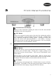
3 Front Panel Functions Vacuum Fluorescent Display Display provides information regarding the status of the CD1 and track/time information for the disc being played. ‘RPT’ Button Allows you to repeat the current track or the entire disc continuously until the feature is cancelled by pressing the RPT button or pressing ‘■’. The RPT button steps sequentially through the available options. Pressing the button once repeats the current track, displaying REPEAT 1 in the display.
‘ ■’ Button This button stops a disc that is playing and resets the player, i.e. if play is resumed, the disc will start over from the first track. ‘ ’ Button Pressing this button returns to the beginning of the current track. Pressing twice quickly in succession returns to the beginning of the previous track. The new track number is shown in the display. ‘ ’ Button Pressing this button advances to the beginning of the next track. The new track number is shown in the display.
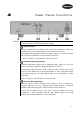
4 Rear Panel Functions Caution! Please make all changes at minimum volume setting. Only increase the volume after the connections have been made. Digital Output Using a standard 75Ω coax digital cable with RCA termination, connect the digital output to the coax digital input on the external D/A converter. These high quality gold plated sockets are highly conductive, corrosion resistant, and provide less potential for corrosion induced distortion. Refer to Chapter 13 “Specifications” for more details.
The pin assignments of the balanced XLR output connectors are as follows: Pin 1: Signal ground Pin 2: Signal + (non-inverting) Pin 3: Signal – (inverting) Shield ground: Chassis ground Caution! Please refer to the operating manual of your preamplifier; integrated amplifier or receiver to verify that the pin assignments of the input connectors correspond to the CD1 balanced outputs. In the event that they are not compatible, the interconnecting cable will need to be altered to suit.
AC Mains Input and Fuse AC Mains Input An IEC-standard mains input is provided at the rear of the unit. The AC cord set is removable, allowing you to upgrade to a cord set of your preference. Caution! Prior to connection to the AC mains, please check the voltage label on the rear panel to ensure that your unit conforms to the power supply in your area. Never attempt to connect the unit to the incorrect voltage. Severe damage can result from applying incorrect voltage to the unit.
5 Remote Control Functions The CD1 comes supplied with a 36 button Perreaux Universal infrared remote control. The remote control uses 2 x AAA batteries and may be changed by removing the black perspex insert. Note: Press the button on the remote to select the code-set required to control the CD1. The CD1 uses the following functions: Open/Close When the disc drawer is closed, pressing this button opens the drawer. To close the drawer, press the button again.
Direct Access These numeric buttons are used to directly access a track from the remote control instead of stepping through using the TRACK buttons. The first ten tracks on a disc can be selected by pressing the corresponding button on the remote control. For example, to play the eighth track, press . When accessing track numbers greater than 10, press followed by the track number. For example, to select track 15, press followed by and . The number of the selected track will appear on the display.
Random This instructs the CD1 to play tracks from the entire disc in random order. Once all of the selections have been played once, the disc will stop playing, unless the REPEAT function is utilised, in which case the random play will continue until the STOP button is pressed. When the RANDOM feature is in use, the word RANDOM is shown in the display.
6 Special Design Philosophies Perreaux has been designing and manufacturing only the highest quality audio componentry for more than a quarter of a century. Technology has continued to evolve rapidly over that time and our knowledge and application of design, materials and manufacturing techniques has advanced in tandem with this. Today’s Perreaux range comes closer to fulfilling our shared vision than at any other time in the past.
“Form and function” are both tough masters. That is why our amplifier heat sinks are not hidden, but instead feature prominently in all our designs. We make no excuses for producing some of the most distinctive high-end audio products on the planet. We let “form and function” blend together in perfect harmony. This surely is the essence of true minimalist utilisation.
7 Special Design Features Rugged Build Quality M echanical strength has been a hallmark of Perreaux products since the company first started production back in 1974. The concept behind the physical design and construction is that each structural member should contribute to both rigidity and performance. Multiple Regulated Power Supplies There is a separate regulated power supply for each section of the CD player.
8 Interconnects and Speaker Cables Maximising System Potential An often-ignored area in high fidelity systems is the cabling connecting the various components. Interconnect leads should be high quality cable with substantial terminations. Gold plate is inherently resistant to corrosion, and an excellent conductor. The presence of corrosion induces distortion and poor conductivity will seriously interfere with sound quality.
9 Care and Maintenance The CD1 has been designed to provide many years of trouble free enjoyment. Note: Please switch the unit off and remove the cord-set from the rear of the amplifier before attempting to clean your CD1 in the manner described below. Never apply liquid directly to the CD1. Never use abrasives. Never rub in a circuilar motion. Cover The cover features a durable, high quality powder-coat finish. To remove finger marks and dirt, lightly rub the surface with a soft cloth.
10 Warranty Information and Obtaining Service 1 Year Limited Warranty The Perreaux CD1 is warranted to be free from defects in material and workmanship under normal use to the original purchaser for a period of 1-year (365) days from the date of purchase from an authorised dealer or distributor.
11 Extended Warranty Registration Form Please complete this form and either fax, mail or scan and e-mail it to Perreaux Industries Ltd. Fax: +64 3 489 2976 M ail: Perreaux Industries Ltd PO Box 305 M osgiel Dunedin 9053 New Zealand E-mail: info@perreaux.com Alternatively, complete the online Warranty Registration Form on our website – www.perreaux.com.
12 Cause and Elimination of Hum Faultfinding Your System Hum is a particularly annoying form of noise in any high fidelity system and at some time has been experienced by many of us. Hum may result from a number of different situations and to make matters worse maybe caused by a seemingly illogical combination of circumstances. One or more of three specific causes creates hum in the system.
When a piece of equipment is supplied with a three pin mains/line supply lead all three pins must be connected in the correct fashion - see your dealer if in doubt. Check all interconnecting signal leads for good connections, both internal connections and firm contact with the sockets. While the centre pin may make firm contact, it is very important that the outer contact is also firm. Never remove the earth/ground wire from the mains/line supply of any piece of equipment.
Step 1 – Loudspeakers SOURCE AMPLIFIER A B Change the loudspeaker leads from one loudspeaker to the other. If the fault remains in loudspeaker ‘A’, then loudspeaker ‘A’ is at fault, go no further. If the fault now appears in loudspeaker ‘B’ then the problem lies further up the line. M ove on to step 2. Step 2 – Loudspeaker Leads SOUR CE AMPLIF IER A B Change the loudspeaker leads completely from left channel to right and from right channel to left by now swapping them at the amplifier output.
If the fault stays in loudspeaker ‘A’, then it is probable that the fault may exist within the amplifier. Caution! Changing of any connectors must be carried out at a minimum volume setting. Only increase the volume after the connections have been changed. Step 3b – Inputs (Interconnects) SOURCE AMPLIFIER A B Change the interconnect leads completely from left channel to right and from right channel to left by now swapping them at the source component’s output.
Faultfinding Flowchart Fault in loudspeaker A Swap loudspeaker connections Fault in loudspeaker A? YES Loudspeaker A at fault YES Loudspeaker cable at fault NO Loudspeaker cable at fault NO Input source at fault NO Swap amplifier outputs Fault in loudspeaker B? NO Restore speaker cables to original connections Swap amplifier source input channels Fault in loudspeaker A? YES Swap source output channels Fault in loudspeaker A? YES Amplifier at fault 27
13 Specifications The CD1 specifications are detailed in brief and then subsequently in more detail. In the detailed version, we attempt to explain the significance of each specification. The correlation between published specifications and sonic unreliable. A list of numbers reveals virtually nothing. measurements must be subject to qualitative as well interpretation. M easurements of the CD1 reveal excellent standards.
Mains Input Voltage 100V, 110V, 120V, 220V, 230V or 240V AC at 50Hz or 60Hz (Set within the CD1 at time of manufacture) Dimensions Width...............................................................................................430mm (16.9”) Height ................................................................................................106mm (4.2”) Depth...............................................................................................323mm (12.
Intermodulation Distortion...................................................... 0.004% @ 1kHz A complex form of distortion occurring when two signals at different frequencies are produced at the same time, creating additional signals at various other frequencies and at various amplitudes. Signal to Noise Ratio............................................................................... >105dB The ratio of desired signal to noise signals present in the output.
14 Physical Dimensions 31
15 Contact Details For more information please contact your Perreaux dealer, or contact: Perreaux Industries Ltd PO Box 305 M osgiel Dunedin 9053 New Zealand Ph: +64 3 489 2975 Fax: +64 3 489 2976 E-mail: info@perreaux.com Internet: www.perreaux.
Installation Notes 33