Prisma SM6 MkII Balanced Preamplifier Owners Manual
Perreaux Industries Limited makes no warranty for the use of its products, other than those expressly contained in the warranty detailed herein. The Company assumes no responsibility for any errors which may appear in this document, reserves the right to change products or specifications detailed herein at any time without notice, and does not make any commitment to update the information contained herein.
i Introducing the Perreaux SM6 MkII Preamplifier Congratulations on your Perreaux SM 6 M kII purchase. To realise the full potential of your unit you need to appreciate all aspects of its operation. Before installing the SM 6 M kII into your system, read the entire manual carefully. Endeavour to understand every detail by familiarising yourself with the controls and features as you read. You will find it easier to install using the relevant sections of this manual as a reference.
ii Important Safety Instructions Note: All safety and operation instructions should be read carefully before the SM6 is operated. Keep the Owners Manual in a safe place for future reference. The SM 6 should not be used near water, for example near a bathtub, kitchen sink, in a wet basement, near a swimming pool, etc. M ounting to a wall or ceiling should be via a heavy-duty bracket or shelf designed for audio equipment use.
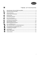
iii Table of Contents i ii iii 1 2 3 4 5 6 7 8 9 10 11 12 13 14 15 Introducing the Perreaux SM6 Preamplifier...............................................................3 Important Safety Instructions ........................................................................................4 Table of Contents ..............................................................................................................5 Unpacking and Placement...............................................................
1 Unpacking and Placement The SM 6 is packaged for maximum protection. Please carefully read the instructions below before proceeding to unpack the unit. Be extremely careful. Unpacking Procedure Note: Inspect both ends of the cardboard box and open at the end without the central staple by slitting the reinforced tape at either side. Fold back the flaps and tip the package on end and the inner box will slide out.
2 Instant Install If you are like us, the first thing you will want to do is to play your favourite piece of music through your new SM 6. The following instructions are written to enable you to achieve this as quickly as possible. These are not comprehensive instructions, but are designed to enable you to play music now! Note: Please take the time to read the SM6 manual thoroughly as it incorporates many features, which will enhance its operation.
Test for undesirable noises Without any program source material, slowly increase the SM 6 volume listening for any undesirable noises. After establishing that there are no problems, return the SM 6 volume level back to zero. Play your source material Start your source material playing. Increase the volume Slowly increase the volume on the SM 6 to achieve a comfortable listening level.
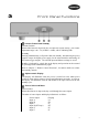
3 Front Panel Functions Volume Control and Standby Volume Control When either button is depressed, they will alter the volume setting. The volume adjustment range is 00 – 59 (-95dB to +18dB), with 47 indicating 0dB. Standby Pressing simultaneously will put the SM 6 into standby, disconnecting all power supplies except the digital power supply for the microcontroller and turning off the remote trigger outputs. The selected input and balance settings are saved.
Caution! Input D (HT Loop) fixes the output to 0dB, as it is a home theatre bypass. Please ensure the level is suitably attenuated by the upstream processor or receiver before selecting this input. Note: The source selector has six positions and supplies the chosen source to the Pre/Balanced outputs and Tape outputs.
4 Rear Panel Functions Caution! Observe precautions regarding volume control settings. Please make all changes at minimum volume setting. Only increase the volume after the connections have been made. Balanced Inputs Accepts a signal from a source component with balanced outputs via high quality XLR connectors.
Note: The position of the Balanced Input switch has no bearing on the balanced output, it only selects which input to use for input A. Set the Balanced Input switch to ON only when using the balanc ed input.. Refer to Chapter 13 “Specifications”, for detail on input sensitivity and impedance. Unbalanced Source Inputs Accepts a standard single-ended input (RCA) from source components with single-ended analogue outputs.
The pin assignments of the balanced XLR output connectors are as follows: Pin 1: Signal ground Pin 2: Signal + (non-inverting) Pin 3: Signal – (inverting) Shield ground: Chassis ground Caution! Please refer to the operating manual of your amplifier to verify that the pin assignments of the input connectors correspond to the SM6 balanced outputs. In the event that they are not compatible, the interconnecting cable will need to be altered to suit.
The plug must follow the specifications as per the diagram below: AC Mains Input An IEC-standard mains input is provided at the rear of the unit. The AC cord set is removable, allowing you to upgrade to a cord set of your preference. Caution! Prior to connection to the AC mains, please check the voltage label on the rear panel to ensure that your unit conforms to the power supply in your area. Never attempt to connect the unit to the incorrect voltage.
5 Remote Control Functions The SM 6 comes supplied with a 36 button Perreaux Universal infrared remote control. The remote control uses 2 x AAA batteries and may be changed by removing the black perspex insert. Note: Press the button on the remote to select the code-set required to control the SM6.
Note: Balance settings are stored when the unit is put into standby. / Input A Source Select Depressing selects source input A and the relevant code-set to control the compact disc player. Pressing selects source input A only. Source input A is indicated by “IA” on the display of the SM 6. / Input B Source Select Depressing selects source input B and the relevant code-set to control the tuner. Pressing selects source input B only. Source input B is indicated by “IB” on the display of the SM 6.
Scroll Source Up Pressing this button scrolls the source input up, selecting in the order: IA IB IC HT IE IF Scroll Source Down Pressing this button scrolls the source input down, selecting in the order: IA IF IE HT IC IB 17
6 Special Design Philosophies Perreaux has been designing and manufacturing only the highest quality audio componentry for more than a quarter of a century. Technology has continued to evolve rapidly over that time and our knowledge and application of design, materials and manufacturing techniques has advanced in tandem with this. Today’s Perreaux range comes closer to fulfilling our shared vision than at any other time in the past.
“Form and function” are both tough masters. That is why our amplifier heat sinks are not hidden, but instead feature prominently in all our designs. We make no excuses for producing some of the most distinctive high-end audio products on the planet. We let “form and function” blend together in perfect harmony. This surely is the essence of true minimalist utilisation.
7 Special Design Features Rugged Build Quality M echanical strength has been a hallmark of Perreaux products since the company first started production back in 1974. The concept behind the physical design and construction is that each structural member should contribute to both rigidity and performance. Balanced Design The SM 6 is a truly balanced preamplifier, from input to output. The positive and negative halves of the signal never touch, remaining balanced throughout all stages.
8 Interconnects and Speaker Cables Maximising System Potential An often-ignored area in high fidelity systems is the cabling connecting the various components. Interconnect leads should be high quality cable with substantial terminations. Gold plate is inherently resistant to corrosion, and an excellent conductor. The presence of corrosion induces distortion and poor conductivity will seriously interfere with sound quality.
The rejection ratio achieved is described in minus dB. The CM RR of a system follows the formula 20Log(Voutput/Vinput). In other words a CM RR of –40dB means that all garbage entering the unit will be made 100 times smaller. The piece of equipment with poorest CM RR will effectively determine the hum and RFI level of the system. Effectively the weakest link in the chain. Highest quality audio systems should quote a CM RR figure of –80dB or better.
9 Care and Maintenance The SM 6 has been designed to provide many years of trouble free enjoyment. It is important to keep the exterior of the unit clean. Note: Please switch the unit off and remove the cord-set from the rear of the amplifier before attempting to clean your SM6 in the manner described below. Never apply liquid directly to the SM6. Never use abrasives. Never rub in a circular motion. Cover The cover features a durable, high quality powder-coat finish.
10 Warranty Information and Obtaining Service 1 Year Limited Warranty The Perreaux SM 6 is warranted to be free from defects in material and workmanship under normal use to the original purchaser for a period of 1-year (365) days from the date of purchase from an authorised dealer or distributor.
11 Extended Warranty Registration Form Please complete this form and either fax, mail or scan and e-mail it to Perreaux Industries Ltd. Fax: +64 3 489 2976 M ail: Perreaux Industries Ltd PO Box 305 M osgiel Dunedin 9053 New Zealand E-mail: info@perreaux.com Alternatively, complete the online Warranty Registration Form on our website – www.perreaux.com.
12 Cause and Elimination of Hum Faultfinding Your System Hum is a particularly annoying form of noise in any high fidelity system and at some time has been experienced by many of us. Hum may result from a number of different situations and to make matters worse maybe caused by a seemingly illogical combination of circumstances. One or more of three specific causes creates hum in the system.
When a piece of equipment is supplied with a three pin mains/line supply lead all three pins must be connected in the correct fashion - see your dealer if in doubt. Check all interconnecting signal leads for good connections, both internal connections and firm contact with the sockets. While the centre pin may make firm contact, it is very important that the outer contact is also firm. Never remove the earth/ground wire from the mains/line supply of any piece of equipment.
Step 1 – Loudspeakers PREAMPLIFIER AMPLIFIER A B Change the loudspeaker leads from one loudspeaker to the other. If the fault remains in loudspeaker ‘A’, then loudspeaker ‘A’ is at fault, go no further. If the fault now appears in loudspeaker ‘B’ then the problem lies further up the line. M ove on to step 2.
If the fault stays in loudspeaker ‘A’, then it is probable that the fault may exist within the amplifier. Caution: Changing of any connectors must be carried out at a minimum volume setting. Only increase the volume after the connections have been changed. Step 3b – Inputs (Interconnects) PREAMPLIFIER AMPLIFIER A B Change the interconnect leads completely from left channel to right and from right channel to left by now swapping them at the source component’s output.
Faultfinding Flowchart Fault in loudspeaker A Swap loudspeaker connections Fault in loudspeaker A? YES Loudspeaker A at fault YES Loudspeaker cable at fault NO Loudspeaker cable at fault NO Input source at fault NO Swap amplifier outputs Fault in loudspeaker B? NO Restore speaker cables to original connections Swap amplifier source input channels Fault in loudspeaker A? YES Swap source output channels Fault in loudspeaker A? YES Amplifier at fault 30
13 Specifications The SM 6 specifications are detailed in brief and then subsequently in more detail. In the detailed version, we attempt to explain the significance of each specification. The correlation between published specifications and sonic unreliable. A list of numbers reveals virtually nothing. measurements must be subject to qualitative as well interpretation. M easurements of the SM 6 reveal excellent standards.
Audio Connections Audio Inputs Unbalanced:................................................................... 6 pairs RCA connectors Balanced: ......................................................................... 1 pair XLR connectors Audio Outputs Unbalanced:................................................................ 2 pairs RCA preamp level .........................................................................................2 pairs RCA line level Balanced:.....................................
Gain Resolution...........................................................................................1.5dB This is the change in gain between each successive volume setting (i.e. ‘46’ is -1.5dB, ’47’ is 0dB, ‘48’ is +1.5dB). The gain resolution is linear throughout the entire gain range. Total Harmonic Distortion (THD+N) .......................... <0.
Input Sensitivity........................................................................................ 200mV Indicates the amount of input voltage required to drive the unit to its rated output. Due to the gain setup of the SM 6, it is able to achieve its rated output even from the lowest of input levels. Input Overload ........................................................................................ 3.
14 Physical Dimensions 35
15 Contact Details For more information please contact your Perreaux dealer, or contact: Perreaux Industries Ltd PO Box 305 M osgiel Dunedin 9053 New Zealand Ph: +64 3 489 2975 Fax: +64 3 489 2976 E-mail: info@perreaux.com Internet: www.perreaux.
Installation Notes 37