
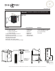
Specification Sheet

INSTALLATION INSTRUCTIONS
Preparation for the installation.
Flush the pipework before
installing this tapware.
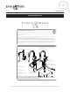
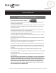
Once unpacked, remove nuts and clamping
plate ready for installation
IMPORTANT INFORMATION
Before you proceed... We recommend you engage the services of a registered plumber to install this
product.
Perrin & Rowe taps require a maximum inlet pressure supply of 75psi. For installations where the
inlet water supply pressure is ever above 75psi, pressure-limiting valves must be installed prior to
this tap.
It is essential that the information contained herein is carefully read and understood prior to
installing and operating this tap.
Congratulations on the purchase of your Perrin and Rowe Kitchen Product. Correctly installed
and with sensible care, this product will give you many years of trouble free service.
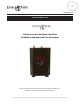
The Mini Hot Dispensers Collection
Installation & User Guide
•
•
THREADED STUD
CLAMPING PLATE
NUT
BASE SEAL
WORK
SURFACE
NYLOCK NUT
BOX
SPANNER
(PROVIDED)
1 3/4" MAX
1
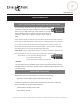
Mounting dispenser:
• Feed the flexible connections
through the ø1
1
/
4
" work surface hole
ensuring the base seal is in place
between tap and mounting surface.
• Ensure the base ring and tap are
orientated correctly, Hot water lever
should rotate to point forwards. The
spout fixing screw should be at the
back.
• Secure by using the clamping plate
and nuts. (box spanner is provided)
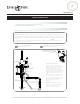
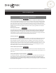
Attach the flow regulator
9
/
16
" to the
Cold inlet and then connect the
9
/
16
"
flexible hose end to the flow
regulator.
Ensure all connections are firmly
tightened.
Consult the guide provided with the
heater tank to ensure correct
positioning and installation.
BASE RING
ENSURE THE SILICONE TUBE
PROTECTOR IS IN PLACE,
CENTRAL AGAINST THE BASE
OF THE TAP.
9/16"
COLD IN
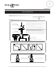
3
Silicone Hose
Trim the silicone hose to the right length for the installation. It must not be pulled taught, too
slack leading to a 'U' bend or twisted. Please make sure the tube isn't pinched between the
threaded stud and the braided hose as this may cause flow restriction. If the silicone is not
installed correctly it may effect the performance of the system.
4
Operation
For instant hot water,
press down on the
lever/button and rotate
handle forward.
Once finished, release the
handle and the valve will
automatically close.
2
G3/8"
FEED TO
HEATER TANK
THROUGH FILTER
SILICONE TUBE
HOT FEED BACK
TO THE TAP
Connections to the filter (U.1106) and heater tank U.1998:
(See separate filter guide and heater tank installation for
further installation instructions)
• Mount the filter housing in an accessible location using
either screws in the bracket or the adhesive pad, ensuring the
mounting area is clean by using the wipe provided.
• Once the mains connections are made fit the G3/8" braided
hose to the filter as shown.
• Connect the silicone tube to the barbed connection on the
top of the heater tank as shown. (SEE NOTE 3 BELOW)
IMPORTANT: During installation the tank should remain
unplugged. The tank must be filled with water before power is
connected. A 'dry start' will void the warranty.
Avoid kinking tubes during installation as the resulting
restrictions could reduce flow and cause malfunctioning of
the expansion chamber. Do not use pipe sealing compounds on
any connections. These can foul the internal mechanics and
may cause objectionable taste and odor. Plumbing connections
must comply with all sanitary, safety and plumbing codes.
AVOID TRAPPING
SILICONE HOSE
BETWEEN STUD &
BRAIDED HOSES
SILICONE
TUBE
RETAINER
CLIP
FLOW REGULATOR
9/16" FEMALE - MALE
9/16" FLEXI-HOSE
FLOW REGULATOR
O
3/8" COMPRESSION SERVICE VALVE
O3/8" COMPRESSION
SERVICE VALVE
ConsultyourlocalHouseofRohlshowroomforadditionalinformationandspecications.Forcompletewarrantydetailsandalistofshowrooms,gotohouseofrohl.com
houseofrohl.com