DO NOT PRINT THIS PAGE RSC Part #: 400-002 Description: Manual PIG00-11115 Material: 100g Material Color: White Printing/Ink Colors: Black Finishing: Die Cut, Fold, 2 Saddle Stitch, and Bulk Pack Updated by: MW Created by: JC Initial Creation Date: 3/18/2013 Approved by: J Weinstein Date Approved: 12/12/2016 Program used: INDESIGN CC Revision: 003 ECO: RSC15209 Revision Description: Revise Collar Illustrations Revision Date: 12/12/2016
Operating Guide PIG00-11115 YardMax® Rechargeable In-Ground Fence™ 5 4 6 3 7 A B 2 1 8 9 10 Please read this entire guide before beginning
Thank you for choosing PetSafe® Brand. You and your pet deserve a companionship that includes memorable moments and a shared understanding. Our products provide you with the tools and technologies to successfully train your pet. If you have any questions about our products or training your pet, please visit our website at www.petsafe.net or contact our Customer Care Center at 1-800-732-2677. To get the most protection out of your warranty, please register your product within 30 days at www.petsafe.net.
This PetSafe® In-Ground Fence™ system is not a solid barrier. This system is designed to act as a deterrent to remind pets by static correction to remain in the boundary established. It is important that you reinforce training with your pet on a regular basis. Proper fit of the receiver collar is important. A receiver collar worn for too long or made too tight on your pet’s neck may cause skin damage, ranging from redness to pressure ulcers. This condition is commonly known as bed sores.
Table of Contents Components ������������������������������������������������������������������������������������������������������������������������������������������������������������������������������������������������������������������������5 Other Items You May Need �������������������������������������������������������������������������������������������������������������������������������������������������������������������������������������������5 Overview ������������������������������������������
Components rating geable In-Gro und Fence Receiver Charger (6 ft.) After opera verifying labels tion at the Receiver Collar boundary, conne to identi the Bounctions to fy the Boun use the the Trans dary dary Wire to the Wire conve Surge Prote conne mitter and wires nient to have ctor. This ctions become will disco should any be nnect of the ed.
Overview The YardMax® system allows you to safely keep your pet within the boundary you set. Although the technology has come a long way, we have safely used static correction for decades and helped millions of pets live happier, healthier and more active lives. An important thing to note, even before we get started, is that you should always remove the receiver collar from your pet while inside or when the system is not in use.
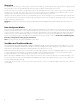
YardMax® Mode (A) Boundary Wire Static Correction Zone (Infinite Containment Area) Pet Area 30% More Yard Than Traditional Mode Warning Zone Traditional Mode (B) Boundary Wire Exclusion Area Non-Containment Area Pet Area Warning Zone Static Correction Zone Static Correction Zone (Finite Containment Area) www.petsafe.
Operating Guide Step 1: Have Your Utilities Marked 1A Buried Cable 1. Call your utility company to have your utility lines marked. If you have neighbors using an in-ground pet containment system, you will want to ask them where the boundary is located. Trust us, you really do not want to skip this step. 2. Make a plan for how you will work around any large metal objects (like sheds) or wires. You can cross utility lines but only at 90° angles (1A).
2. Once you have chosen an outlet and before plugging anything in, go to your breaker box and turn the power off to that outlet. 3. Then, back at the outlet, remove the center screw that holds the outlet cover in place. 4. Plug the surge protector into the lower outlet. 5. Using the large screw provided, secure the surge protector to the outlet. 6. At the breaker box, turn the power back on to the outlet. 7. Next, you will mount the transmitter somewhere within 5 ft. of the surge protector.
Step 4: Design Your Boundary Zone 4A Basic Planning Tips • Always design your layout, position the boundary wire and test the system as outlined in this guide before burying the boundary wire. You do not want to find out after burying the wire that there is a problem with your layout or a loose connection somewhere. • The boundary wire must start at the fence transmitter and make a continuous loop back to it (4A). • Always use gradual turns at the corners with a minimum 3 ft.
YardMax® Mode (A) Layouts Sample 1 4E The YardMax Fence system can only be used with a single loop layout. C Sample 1(4E): Full Perimeter Loop With a full perimeter loop, YardMax mode allows your pet to maximize the pet area and roam the entire property freely and safely. B Sample 2 (4F): Full Perimeter Loop Using Existing Fence This layout allows you to include your existing fence as part of your layout and keep your pet from jumping out or digging under your existing fence.
Sample 4 (4H): Front Yard or Back Yard Only (Double Loop) From the fence transmitter, run the wire to point A, then to point B and so on (B to C to D to E to F). Next, make a U-turn and follow your path all the way back to point G, keeping the wire separated by at least 5 ft. When you get back to the house (G), make a sharp turn along the side of the house back to point A. Finally, twist the wires from point A and connect them back to the fence transmitter.
Step 5: Position, Twist and Splice the Boundary Wire 5A Once you have designed your layout, the next step is to position the wire along your property. Hold off on burying the wire until you have tested the system first. 1. Start with one end of the wire at the surge protector, but do not plug it in yet. Run the wire outdoors all the way around your planned perimeter and back to the surge protector. 2.
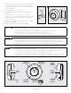
Step 6: Connect the Wires 6A 6B Push Tab Down to Insert Wire Now that the boundary wire has been positioned and spliced, the next step is to connect the wire from inside to the surge protector, and then to the transmitter. 1. Strip ⁄8 in. of insulation from the 2 ends of the boundary wires in order to connect them to the surge protector (6A). 2. Insert the stripped ends into the 2 left red connector holes on the bottom of the surge protector labeled “LOOP” (6B).
ReadyTest® Feature ReadyTest is a startup feature that lets you know the status of the battery as well as the current correction level of the receiver collar. It also checks that all circuits are working correctly. This mode automatically starts every time you remove the receiver collar from the charger, or first turn it on. If the receiver collar is on your pet during the ReadyTest startup, the test will fail and the receiver collar will automatically turn off.
Step 8: Test the Fence Direction 8A You will want to verify that your fence is transmitting in the right direction to contain your pet. You will need to do this test in YardMax® mode, regardless of which mode you plan to use. Set the dial to 3 • The receiver collar should NOT be on your pet when the system is tested. Your pet may receive an unintended correction. • To prevent an unintended correction for your pet, test the boundary location and width after any change. 1.
Step 9: Test the Receiver Collar Northern climates can affect the range of the signal. In YardMax® mode, excessive snowfall (>1½ ft.) may place your pet outside the signal field allowing your pet to leave the pet area. You may need to switch to Traditional mode or increase the boundary width until the snow recedes. Test the Receiver Collar—YardMax Mode 9A In YardMax mode (A), the warning zone starts at the boundary wire. The higher the boundary width setting, the wider (and taller) the warning zone.
Test the Receiver Collar—Traditional Mode 9D These steps are very similar to the ones we used in Step 8. 1. Set the fence transmitter to Traditional mode (B) and turn the boundary width dial up to 7 (9D). 2. Make sure that the static correction on the receiver collar is set to level 6. 3. Place the test light tool against the receiver collar contact points and hold the contact points facing upwards. 4. Hold the receiver collar at your pet’s neck height (9E). 5.
Step 10: Bury the Boundary Wire • Underground cables can carry high voltage. Have all underground cables marked before you dig to bury your wire. In most areas, this is a free service. Avoid these cables when you dig. • Before you begin installing the boundary wire, turn the fence transmitter off and unplug the adapter from the surge protector. Burying the boundary wire is recommended to protect it and prevent disabling the system. 10A 1. Cut a trench 1–3 inches deep along your planned boundary.
Cross Hard Surfaces (driveways, sidewalks, etc.) • Concrete Driveway or Sidewalk (10C): Place the boundary wire in a convenient expansion joint or create a groove using a circular saw and masonry blade. Place the boundary wire in the groove and cover with an appropriate waterproofing compound. For best results, brush away dirt or other debris before patching. • Gravel or Dirt Driveway (10D): Place the boundary wire in a PVC pipe or water hose to protect the boundary wire before burying.
Step 12: Fit the Receiver Collar Proper fit of the receiver collar is important. A receiver collar worn for too long or made too tight on your pet’s neck may cause skin damage, ranging from redness to pressure ulcers. This condition is commonly known as bed sores. • • • • • • • • • • Avoid leaving the receiver collar on your pet for more than 12 hours per day. When possible reposition the receiver collar on your pet’s neck every 1 to 2 hours.
If the receiver collar fails the ReadyTest® startup, the receiver collar is automatically turned off. Your pet will not be contained. 7. Once the ReadyTest startup is done, the receiver collar will automatically go through an optional PerfectFit Test (Step 7), which lasts for 90 seconds. This mode begins with simultaneous flashing red+ green lights. 8. Place the collar on your pet and adjust the fit. 9. The receiver collar will emit a unique double tone as the contact points touch your pet’s skin.
Phase 1 Day 1—Tone-only Training for Boundary Awareness 13A Perform 3 training sessions per day, each lasting 10–15 minutes. Goal: To have your pet learn that the boundary flags and warning tone from the receiver collar define the new pet area. Setup: • Program the static correction level on the receiver collar to level 1, which is tone-only training mode. • Put a separate non-metallic collar on your pet’s neck below the receiver collar and attach a leash.
Steps: 1. Repeat steps 1–3 in Phase 1, this time allowing your pet to stay in the correction zone long enough to be corrected. 2. Observe whether or not your pet seems to feel the correction. A slight change in your pet’s behavior, such as looking around in curiosity, scratching at his collar or flicking his ears, indicates your pet’s recognition level. If your pet does not respond to the static correction, confirm that the receiver collar is fitting properly according to Step 12 on page 21. 3.
Phase 4 Days 9 Through 14—Unleashed Supervision Training sessions should start at 10-15 minutes, gradually increasing to over an hour. Your pet is ready for this step only when he or she clearly avoids the entire static correction zone, regardless of any distractions or temptations. During this step, do not leave your pet unattended. Goal: To give your pet free run of the pet area off the leash. Setup: • Adjust the static correction level to the permanent setting appropriate for your pet.
Advanced Features Anti-Linger Prevention The Anti-Linger Prevention feature keeps your pet from staying in the warning zone for long periods of time and draining the receiver collar’s rechargeable battery. Your pet will hear a 2-second warning tone when he reaches the warning zone. If your pet does not return to the pet area after 2 seconds, he will receive a continuous static correction until he returns to the pet area or until the Over Correction Protection feature is enabled.
System Test 14A The system test is used to determine the cause of system problems that have not been addressed elsewhere in this guide. You will need a piece of boundary wire greater than 15 ft. long with 3⁄8 in. of insulation removed from each end to use as a test loop wire. Make a note of your boundary width dial setting, and receiver collar setting before beginning the system test. 5 4 6 3 7 A B 2 1 8 9 10 Follow the steps below to perform the system test: 1.
Wire Break Location Test 15A The following lists identify the common locations where wire breaks occur. Please inspect these areas for signs of damage. Wire breaks in the twisted pair are commonly found: 1. At the wire exit point of the house 2. Where the twisted pair of wire enters the ground from the house, usually caused by string trimmers 3. Where the wires cross sidewalks or driveways due to edging and string trimmers 4.
Receiver Collar Status Indicators The receiver collar light and with the alarm tones are used to determine the operational mode, the battery status and the correction level. Refer to the receiver collar status table below to understand the status lights and tones for the receiver collar. During normal operation, the receiver collar light will flash every 4 seconds to indicate the battery status as shown in the table below.
Troubleshooting 30 The receiver collar is not beeping or correcting. • Make sure the static correction level is set at 2 or above. • Charge the receiver collar and go through the ReadyTest® startup and PerfectFit diagnostic tests. • Check that the fence transmitter power is turned on and the transmitter status light is solid green. If not, perform the “System Test” (page 27). • In YardMax® mode (A), excessive snowfall (>1½ ft.) may place your pet outside the signal field.
Troubleshooting No status light on the fence transmitter and alarm is silent. • Verify that the transmitter power is on. • Check that the power adapter and/or surge protector are plugged in properly. • If the system is plugged into a GFCI outlet, check to see if the circuit has been tripped. Reset the GFCI circuit if required. • Verify that the outlet is working properly by plugging in a known working item such as a radio.
Terms of Use and Limitation of Liability 1. Terms of Use This Product is offered to you conditioned upon your acceptance without modification of the terms, conditions and notices contained herein. Usage of this Product implies acceptance of all such terms, conditions, and notices. 2. Proper Use This Product is designed for use with pets where training is desired. The specific temperament of your pet may not work with this Product.
Warranty One Year Non-Transferrable Limited Warranty This Product has the benefit of a limited manufacturer’s warranty. Complete details of the warranty applicable to this Product and its terms can be found at www.petsafe.net and/ or are available by contacting your local Customer Care Center.
Layout Grids 34 1-800-732-2677
www.petsafe.
Radio Systems Corporation 10427 PetSafe Way Knoxville, TN 37932 1-800-732-2677 www.petsafe.net For a list of patents protecting this product, please visit: http://www.petsafe.