
Operation Manual

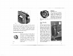

1.
The
Head
(Fig.
12).
Open
the
hinged
face
cover
plate.
2.
The
Arm
(Fig.
13).
Lubricate
all
points
marked
thus
0.
3.
The
Needle
Plate.
Take
out
the
screws
and
remove
the
plate.
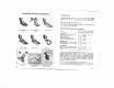
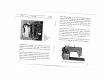
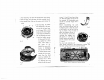
4.
The
Hook
(Fig.
14).
Move
the
needle
bar
to
its
high
est
and
tilt
the
head
over
on
its
hinges.
With
a
small
brush
dust
the
hook.
Apply
a
few
drops
of
paraffin
to
the
race
between
the
hook
II
and
the
bobbin
carrier
IV;
then
work
the
mach
ine
rapidly
for
a
short
while.
Now
apply
a
few
drops
of
oil.
Should
this
prove
inef
fective
in
dislodging
any
dirt
from
the
hook,
or
should
thread
ends
impede
the
free
move
ment,
then
the
hook
must
be
carefully
dis
mantled.
This
is
done
by
removing
the
race
guide
Ill,
after
the
small
screws
1,
2
and
3
have
been
taken
out.
Now
the
bobbin
carrier
IV
can
be
removed.
All
dismantled
parts
should
be
carefully
wiped
with
a
clean
rag.
Before
reassembling
the
parts
move
the
thread
take-up
lever
to
•
•
.
.
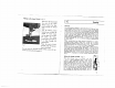
Fig.
16
its
highest
point
so
that
the
point
I
of
the
hook
is
on
the
left,
and
on
top,
as
shown
in
Fig.
14.
Then
re
place
the
bobbin
carrier
IV
into
the
hook
II,
and
let
the
retaining
key
engage
into
the
groove
n
—
see
Fig.
14.
Finally,
replace
the
guide
Ill
and
fix
it
down
with
screws
1,
2
and
3.
You
must
also
lubricate
all
Fig.
17
other
points
indicated
in
the
illustrations,
making
sure
that
after
oiling
oIl
ports
ore properly
replaced.
Ii’
Fig.
14
Fig.
15
Fig.
18
View
of
Underside
of
Machine
Bedplote
16
17