
Installation Guide
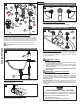

ENGLISH
ENGLISH
7
8
9
10
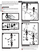
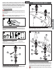
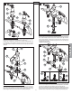
7 HANDLE ATTACHMENT
Place Plastic Seal Rings (7A) against the bottom of Handle Hubs (7B). Connect Handles
(7C) onto Valve Adapters (7D).
Be sure Valves and Levers are in the “OFF” position. Secure handles by holding the
Lever (7E) in place and tighten the Hubs (7F) by rotating them in a clockwise direction.
To remove handles, rotate Hubs (7F) in a counterclockwise direction.
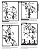
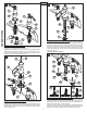
8 SPOUT BODY ATTACHMENT
Insert Lift Rod (8A) into hole at the top of Spout (8B). Place Plastic Seal Ring (8C)
against the bottom of Spout Base (8D). Place Spout Base (8D) against the bottom of
Spout Body (8E). With Spout (8F) facing forward, carefully install the Lift Rod (8A) and
Shank (8G) through the center hole of sink (8H).
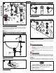
9 SECURING SPOUT BODY
From underneath sink, secure Spout Body (9A) by placing Metal Washer (9B) and
threading Mounting Nut (9C) onto Spout Shank (9D). Make sure that the bumps on
Metal Washer (9B) are facing up. Make sure Lift Rod (9E) moves freely. Be sure Spout
Body (9A) is centered and facing forward and tighten the Mounting Nut (9C) until Spout
Body (9A) is firmly secured to sink.
Caution: Do not over tighten!
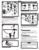
10 HOSE CONNECTION
From underneath sink, push the Center Connector (10A) onto receiving Tube (10B),
until unable to push any further. Pull down on the quick connect housing (10A). If the
housing and the Inner Collet (10C) separate slightly but do not pull off receiving Tube
(10B), the connection is secure.
Slide the End Connectors (10D) with arrow (10E) pointing up onto the Valve Bodies
(10F). Push the End Connectors (10D) all the way up until completely seated. Be
careful not to damage O-Rings (10G).
3
7C
7C
7B
7A
7B
7E
7D
7A
7D
7F
9A
9E
9C
9B
9D
8A
8B
8C
8A
8G
8H
8D
8E
8F
10B
10B
10A
10D
10F
10F
10G
10G
10E
10D
10A
10B
10C
10A