
User guide

ENGLISH
ENGLISH
ENGLISH
7
8
9
10
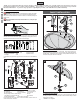
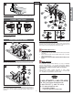
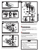
7 VALVE BODY ATTACHMENT
Remove Clip (7A) from Valve Body (7B) and save. From above sink, insert Valve Body
(7B) through Mounting Holes (7C). The HOT valve, labeled with Red Tag (7D), should
be positioned to the left side of the spout.
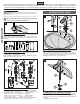
8 VALVE BODY INSTALLATION
Before proceeding, Valve Stems (8A) are to be set in the closed position. From
underneath sink, place Square Washers (8B) onto Valve Shanks (8C) and tighten loosely
with Mounting Nuts (8D). Temporarily place Handles (8E) onto Valve Stems (8A) to
make sure the handle levers are properly aligned to sink. Remove Handles (8E) and
tighten Mounting Nuts (8D) until Valve Bodies (8F) are fi rmly secured to sink.
Do not use handles (8E) to tighten or to rotate Valve Bodies (8F)!
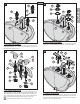
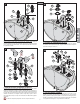
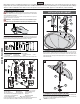
9 VALVE FLANGE ATTACHMENT
Place Seal Base (9A) and Flange (9B) over Valve Body (9C) covering the Valve Body
Washers (9D). Secure by threading the Plastic Nut (9E) onto the Valve Body (9C).
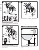
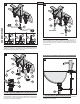
10 HANDLE INSTALLATION
Screw Stem Extender (10A) onto the Valve Stem (10B). With Valves in “Closed” position,
attach Handle Hubs (10C) onto Valve Stems (10B) and tighten Set Screws (10D) with
the Hex Wrench that is provided. Make sure Set Screw (10D) is securely tightened to
Handle (10C).
Attach Decorative Button (10E).
3
7A
9B
9A
9E
9D
9E
9D
9C
9C
10A
10C
10D
10E
10E
10D
10B
10A
10C
10B
9B
9A
7B
7C
8C
8A
8C
8B
8A
8E
8E
8B
8D
8F
8D
8F
7D
7B
7B
7C