IMPORTANT: THESE INSTRUCTIONS ARE TO REMAIN WITH THE HOMEOWNER FOR YOUR SAFETY WARNING: If the information in this manual is not followed exactly, a fire or explosion may result causing property damage, personal injury or loss of life. -- Do not store or use gasoline or other flammable vapours and liquids in the vicinity of this or any other appliance. -- WHAT TO DO IF YOU SMELL GAS • Do not try to light any appliance. • Do not touch any electrical switch; do not use any phone in your building.
Contents CAUTION .............................................................................................................. 3 SAFETY ................................................................................................................ 3 INSTALLATION REQUIREMENTS ....................................................................... 5 TOP STANDOFFS................................................................................................. 5 LOCATING THE FIREPLACE ........................
CAUTION SAFETY FOR YOUR SAFETY - Do not install or operate your Town and Country fireplace without first reading and understanding this manual. Any installation or operational deviation from the following instructions voids the Town and Country FireplacesTM Warranty and may prove hazardous. This appliance and its individual shutoff valve must be disconnected from gas supply piping system during any pressure testing of that system at test pressures in excess of 1/2 psig (3.5 kPa).
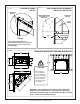
Fig. # 2 COMBUSTIBLE FRAMING AND FINISH WALL ABOVE STANDOFFS STEEL FRAMING MAY USE COMBUSTIBLE FACING MATERIAL IN THIS AREA STANDOFFS NON-COMBUSTIBLE FINISH MATERIAL SEE FIG #7 NON-COMBUSTIBLE ZONE. DO NOT INSTALL ANY COMBUSTIBLE MATERIAL, ELECTRICAL WIRING OR GAS PLUMBING IN THIS AREA. D E F A B C TOP OF LINTEL BAR FIREPLACE FRONT MANTEL CLEARANCE CHART MANTEL * CLEARANCE REF. A 9" D 12" B 6" E 6 3/4" C 3" F 1 1/2" REF. Minimum Clearances to Combustibles: (0 mm) Back standoffs ..
INSTALLATION REQUIREMENTS The Town & Country Fireplace installation and venting must conform to the current CAN/CGA-B149 installation code (in Canada) or the current National Fuel Gas Code, ANSI Z223.1 (in the USA), and approved per local codes. Only qualified (licensed or trained) personnel should install this product. In the state of Massachusetts, only a licensed Plumber and Gas Fitter may install this product. Fig. # 4 Fig.
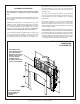
FRAMING AND FINISHING Note: The fireplace must be in place and venting installed before framing in or building an enclosure around the unit. The Town & Country Fireplace must be framed in as described below or totally enclosed with non-combustible material, such as facing brick. Determine the total thickness of facing material to be used. A thickness of 3/4" will allow the finishing surface to be flush with the front of the unit.
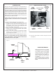
Fig. # 7 CONCRETE BOARD DETAIL Fig. # 8 NON-COMBUSTIBLE RECESSED INSTALLATION DETAIL CONCRETE BOARD NON-COMBUSTIBLE MASONRY TYPE MATERIAL CONCRETE BOARD STEEL STUDS 6" Concrete board (or other noncombustible material) must extend 12" above and 4 1/2" to the sides of the framing edges. Fig. # 9 MINIMUM COMBUSTIBLE FRAMING DIMENSIONS Including Sheetrock CAUTION: When framing for the fireplace, ensure adequate space is provided for the control box. Do not install the control box above the fireplace.
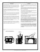
CONTROL BOX Fig. # 10 The gas control system is housed in a control box remote of the fireplace. Flexible conduits attach the control box to the fireplace and house all the plumbing and wiring to the burner. This unique design allows the control box to be mounted in a variety of positions on the right or left side of the fireplace. The box can be framed into the front right or left face or the right or left sidewall of the fireplace enclosure.
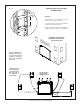
CONTROL BOX LOCATION AND FRAMING DETAIL Fig. # 12 4 1/4" CAUTION: 12" - A 2 foot service access clearance is recommended in front of the control box. - If recessed into a masonry wall, allow for control door and frame removal. - If flush mounted on a masonry wall, allow for conduit to exit out the bottom of control box.
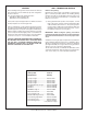
VENTING WALL TERMINATION VENTING Before installing venting for this unit, the installer should read these instructions to insure that the proper vent configuration has been selected. Use only Town and Country Termination kits #: TCVT.WTA - Wall Termination Kit TCVT.RTA - Roof Termination Kit Exterior wall opening: Determine the exact position of the fireplace so that the vent pipe is centred (if possible) between two building framing members. Consult your local building codes prior to proceeding.
Fig. # 14 WALL THIMBLE AND VENT MUST NOT PROTRUDE BEYOND SIDING Wall thimble: Where a vent pipe passes through a combustible wall, a wall thimble/shield must be used to retain insulation and maintain proper clearances. The wall thimble may be cut to length for various wall thicknesses up to 12" thick. Measure the wall thickness including the siding. Trim the shield to match the wall thickness. Position the wall thimble from inside through the 14-1/2" opening.
Vent pipe: Install vent pipe through the wall thimble and attach to flue outlet collar on top of the fireplace. Secure all joints with screws and seal with approved "High Temp." self-adhesive aluminum tape provided (see VENT PIPE SEALANT section). The fireplace position may need to be adjusted to ensure that the vent pipe does not protrude beyond the outer wall or be recessed any more than 12 inches with the inner pipe. Fig.
WALL TERMINATION VENTING CHART Fig. # 17 D A B C Minimum rise Pipe length Maximum run Pipe length Maximum 68 1/2” 24” 18" 1' 74 1/2” 30” 76" 5' 80 1/2” 36” 11' 2 1/8" 10' 86 1/2” 42” 16' 15' 92 1/2” 48” 20’ 10 1/4” 20' For other rise/run combinations see chart below 24" Pipe length minimum NOTE: The vent must not exceed a total length of 68 feet. Any combination of rise and run may be used but must be constrained to the boundaries of this chart.
Fig. # 18 ROOF TERMINATION VENTING CHART D A B C Minimum rise Pipe length Maximum run Pipe length Maximum 68 1/2” 24” 26 5/16" 1' 74 1/2” 30” 84 3/8" 5' 80 1/2” 36” 11' 10 1/2" 10' 86 1/2” 42” 16' 8 1/2" 15' 92 1/2” 48” 21’ 6 5/8” 20' For other rise/run combinations see chart below 24" Pipe length minimum 14 36ARB2 NOTE: The vent must not exceed a total length of 68 feet. Any combination of rise and run may be used but must be constrained to the boundaries of this chart.
ROOF TERMINATION VENTING Fig. # 20 Ceiling opening: A 1) Determine the exact position of the fireplace so that the vent pipe is centered (if possible) between two building framing members. Lay out the vent system path, minimizing the number of elbows and length of vent. Consult your local building codes prior to proceeding. 14 1/2" 2) Cut and frame a 14 1/2" opening in the floor, ceiling and roof where the vent system will pass.
Roof vent terminal: 1) Place the roof flashing over top of the vent pipe and nail securely to the roof using roofing nails, top and sides UNDER shingles, lower end OVER shingles to provide a watershed. Make weather tight by sealing with a roofing compound (see Fig. #21). 2) Place the storm collar down over the vent pipe until it is level. Tighten storm collar for a snug fit. Apply a thick horizontal ring of mastic around the pipe at top of the storm collar (see Fig. #21).
VENT TERMINAL CLEARANCE VENT TERMINAL MINIMUM CLEARANCES TO ADJACENT STRUCTURES Fig. # 22a Minimum clearances to the vent terminal must be maintained as shown in figure #22a & b. Measure clearances to the nearest edge of termination hood. 36" (91.5 cm) 24" (61 cm) NOTE: Vent terminal must not be recessed into a wall or siding. NOTE: LOCAL CODES OR REGULATIONS MAY REQUIRE DIFFERENT CLEARANCES. 24" (61 cm) 48" (122 cm) ADJACENT STRUCTURES OR FENCE VENT TERMINAL MINIMUM CLEARANCES Fig.
VENT PIPE SEALANT Fig. #23 APPROVED "HIGH TEMP." SELF-ADHESIVE ALUMINUM TAPE VENT PIPE INSULATED COLLAR SHIELD (Included) MUST BE USED. SEE SECTION BELOW VENT PIPE SEALANT All outer joints of the vent pipe must be sealed with the approved "High Temp." self-adhesive aluminum tape provided. Wrap the tape completely around the joint and press firmly in place. Fig. #24 INSULATION COVER (2 pcs.) BEND TABS INSULATED COLLAR SHIELD (Included Pt# TC36.
VENT RESTRICTOR ADJUSTMENT Fig. # 26 WALL AND ROOF TERMINATION RESTRICTOR POSITION The vent restrictor is located on the underside of the firebox top. The unit leaves the factory with the vent restrictor wide open. The restrictor is built into the appliance for secondary air flow adjustment. Adjustment enables tuning the airflow for optimum flame appearance and performance for a wide variety of vent configurations.
GAS SUPPLY Caution: The gas line should be installed by a qualified service person in accordance with all building codes. This section is intended as a guide for qualified technicians installing this appliance. Consult local and/or national building codes before proceeding. Recommended Thermostat Wire Size Wire Size Max. Length 14 ga............................. 100 ft. 16 ga.............................. 60 ft. 18 ga.............................. 40 ft. 20 ga.............................. 25 ft. 22 ga....
WINDOW FRAME REMOVAL Warning: Turn off the fireplace, and allow ample time for the unit to cool before proceeding. Caution: The ceramic glass is very fragile, and should be handled with care. Fig # 29 UPPER FIREBOX SHIELD The window frame is held in place by two spring-loaded latches and are operated by a removable handle. The handle is located in the Control Box. 1) Insert the latch handle onto the catch located 6” down from the top corners. Rotate up to disengage each of the two catches.
FIREBOX PANELS INSTALLATION Fig. #32 ADJUSTABLE "V" BRACKET (HERRINGBONE .................. TCPN.7566) (TUSCAN ................................ TCPN.748) (HERITAGE RED................ TCPN.75704) For porcelin panel kit (TCPN.75702) installation see instructions provided with panel kit. The Firebox Panels have to be installed for safe operation. Do not use the fireplace without panels. Unpack and inspect all panels. The panels need to be installed before the logs are in place.
LIGHTING INSTRUCTIONS - Millivolt Valve FOR YOUR SAFETY READ BEFORE LIGHTING WARNING: If you do not follow these instructions exactly, a fire or explosion may result causing property damage, personal injury or loss of life. A. This appliance is equipped with an ignition device which automatically lights the pilot. Do not try to light the pilot by hand. B. BEFORE LIGHTING smell all around the appliance area for gas.
1) HI-LO Flame Adjustment: The HI-LO burner control knob can be rotated in both directions, providing infinite control of gas flow rate to the burner and therefore greater comfort control. The HI setting provides a maximum gas input, and rotating the knob clockwise toward the LO setting will reduce the gas input to a minimum setting. 2) Wall Thermostat - Canada Only (Optional part # GASC.THERMO): Set the wall thermostat to a comfortable temperature. Turn the HI-LO burner control knob to a desired setting.
APPENDIX A Annual Inspection: MAINTENANCE Caution: Turn off gas and electrical power supply (if applicable) and allow ample time for unit to cool before servicing appliance. It is recommended that the fireplace and its venting should be inspected at least once a year by a qualified service person. a) Remove glass panel and log set. Inspect logs and burner assembly for soot buildup. If excessive buildup of soot is present, have a qualified service person inspect and adjust unit for proper combustion.
REPLACEMENT PARTS (WHEN ORDERING, INCLUDE PART NUMBER WITH DESCRIPTION) ITEM DESCRIPTION PART NO. 1............ GLASS FRAME........................... TC36.9520WLD 2............ REPLACEMENT GLASS (c/w gasket) GLAS.2088 .............. GLASS RETAINER, TOP....................... 9050.001 .............. GLASS GASKET KIT ................................. 2087.1 .............. FRAME & GLASS ASSEM.................. TC36.9520 4............ CONTROL DOOR ASSEMBLY .......... TC42.9074 6............
REPLACEMENT PARTS-MILLIVOLT CONTROL ASSEMBLY (WHEN ORDERING, INCLUDE PART NUMBER WITH DESCRIPTION) ITEM ..... DESCRIPTION......................................PART NO. 1............ KNOB, EXT, ON/OFF 1-1/2 .................... 5007.315 2............ KNOB, EXT, HI/LO 1-1/2 ........................ 5007.316 3............ SPARKER, BOX ..................................... 5016.902 4............ FITTING, DISPL.CONN.BLK974.071 ..... 5019.006 5............ CONN, DISPLAY TAB .......................... 5019.0061 6.
REPLACEMENT PARTS - ELECTRONIC CONTROL ASSEMBLY ITEM ..... DESCRIPTION......................................PART NO. 1............ ELECTRONIC, VALVE, NG ...................... 5030.01 2............ ELECTRONIC, IGNITION MODULE......... 5030.02 3............ ELECTRONIC, BATTERY HOLDER ........ 5030.03 4............ ELECTRONIC, AC ADAPTOR.................. 5030.04 5............ ELECTRONIC, WIRE HARNESS ..........5030.05.A 6............ ELECTRONIC, KNOB EXTENSION ......... 5030.06 7............
ELECTRONIC VALVE WIRING DIAGRAM Fig.
Fig. # 40 WALL TERMINATION KIT TCVT.WTA WALL TERMINAL TCVT.9360 WALLSHIELD/CEILING FIRESTOP THIMBLE TCVT.THIMA Fig. # 41 WALL SHIELD/CEILING FIRESTOP THIMBLE TCVT.
Fig. # 42 ROOF TERMINATION KIT TC36.RTA VERTICAL TERMINATION CAP TCVT.9365 STORM COLLAR TC42.90665 CEILING FIRESTOP TCVT.THIMA ROOF SUPPORT BRACKET TCVT.
Fig. # 43 VENT PIPE DIMENSIONS 11" * 10 15/16" 9 1/2" 12" Pipe ............. 10 1/4" 18" Pipe ............. 16 1/4" 24" Pipe ............. 22 1/4" 48" Pipe ............. 46 1/4" TCVT.811X12ADJ 11 1/8" TCVT.811X _ _ 45° 13 13/16" 12 9/16" 8 5/16" 10 5/16" 15 7/8" 7/16" 1 5/16" 13 1/8" TCVT.811XLB45 TCVT.
Fig. # 44 VENT OFFSET CHART A 10 7/8" B C A 12" Pipe......18 5/8"........18" 18" Pipe......22 7/8"........22 3/8" 24" Pipe......27 1/8"........26 1/2" 48" Pipe......44 1/16"......43 1/2" C Adding an adjustable section to pipe will increase offset by 2 1/8" to 6 3/4" 1 1/4” 11 3/8" 1 1/4” B A 16 1/16” 1 1/4” B C 12" Pipe......13 7/16"......23 1/4" 18" Pipe......17 9/16"......27 5/8" 24" Pipe......21 7/8"........31 3/4" 48" Pipe......38 3/4"........
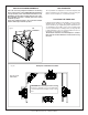
VARIOUS GAS SUPPLY CONNECTIONS Note: Consult local codes before proceeding. Fig. # 47 GASTITETM FLEX LINE WITH REDUCING COUPLING Fig. # 45 FLEXIBLE CONNECTOR WITH SHUTOFF VALVE Fig. # 48 COPPER LINE WITH FLARE FITTING Fig. # 46 BLACK IRON PIPE WITH UNION * USA ONLY Copper piping may only be used in compliance with local codes or, in the absence of local codes, with the following National Fuel Codes: • NFPA54 - Section 2.6.2d • NFPA54 - 2002 - Section 5.6.3.2 • ANSI Z223.1 - 2002 - Section 5.6.3.
VENTED GAS FIREPLACE - NOT FOR USE WITH SOLID FUEL FOYER AU GAZ À ÉVACUATION - NE PAS UTILISER AVEC DU COMBUSTIBLE SOLIDE ANSI Z21.50b-2002 / CSA 2.22b-2002 Vented Gas Fireplaces CAN/CGA 2.17-M91 Gas-Fired Appliance For Use At High Altitudes. Certified for / Certifié pour Canada and U.S.A.
2975 Allenby Rd., Duncan, BC V9L 6V8 Phone: 1-888-223-0088 Web site: www.townandcountryfireplaces.