
User's Manual


10 36ARB2 050505-36
VENTING
Before installing venting for this unit, the installer should read
these instructions to insure that the proper vent con guration
has been selected.
Use only Town and Country Termination kits #:
TCVT.WTA - Wall Termination Kit
TCVT.RTA - Roof Termination Kit
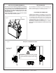
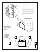
Vent system components approved for use with the Town and
Country Fireplace are shown in Figure #13.
Various combinations of vertical and horizontal runs may be
used. Refer to #
17 and 18 for details. For optimum performance
and ame appearance, keep the vent length to a minimum and
limit the number of elbows. Connections between each vent
system component must be tightly joined, secured with sheet
metal screws and sealed. A horizontal run of vent should have
a 1/4" rise for every 1 ft. of run towards the termination.
CAUTION: UNDER NO CONDITION SHOULD COMBUSTI-
BLE MATERIAL BE CLOSER THAN 1 3/4 INCHES FROM
THE TOP AND 1 3/4 INCHES FROM THE SIDES OF A
HORIZONTAL SECTION AND 1 3/4 INCHES FROM THE
VERTICAL SECTIONS OF THE VENT PIPE.
Vent System Town &
Components Country
12" Pipe Length ........................... TCVT.811X12
18" Pipe Length ........................... TCVT.811X18
24" Pipe Length ........................... TCVT.811X24
48" Pipe Length ........................... TCVT.811X48
18" Adjustable Pipe Length ......... TCVT.811X12ADJ
45° Elbow .................................... TCVT.811XLB45
90° Elbow .................................... TCVT.811XLB90
Wall/Offset Support ..................... TCVT.811XOS
Wall Termination Kit .................... TCVT.WTA
Roof Termination Kit .................... TCVT.RTA
Wall Shield/Ceiling Firestop ......... TCVT.THIMA
Roof Flashing, Adjustable ............ TCVT.811FLADJ
Roof Flashing, Flat ...................... TCVT.811FLFLT
Roof Flashing, Steep ................... TCVT.811FLSTP
or any that ts 11" pipe
Fig. # 13
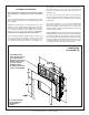
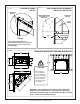
WALL TERMINATION VENTING
Exterior wall opening:
Determine the exact position of the replace so that the vent
pipe is centred (if possible) between two building framing
members. Consult your local building codes prior to proceed-
ing. The vent kit will accommodate up to a maximum wall
thickness of 12 inches.
1) Having determined the position of the replace, cut and
frame a 14 1/2 inch opening centred at a minimum height
of
68 1/2 inches above the oor. The opening may be
round or square. Height of the opening will vary with each
installation. As the horizontal vent run increases, so does
the minimum vertical rise (see Fig. #17).
IMPORTANT: When locating the opening, it should be
noted that vent terminal clearances must be maintained.
See "Vent Terminal Clearances" section for proper clear-
ances.
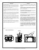
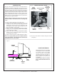
A minimum 2 foot length of pipe is required for any wall termi-
nation. With this minimum vertical rise in combination with a
90° elbow, a maximum horizontal run of 18 inches is permitted
(see Fig. #17 and 18). For longer horizontal runs greater than
18 inches, increase vertical rise appropriately.
The rise and run must be constrained to the boundaries of the
chart shown in gure #17. The horizontal run of vent must have
a 1/4" rise for every 1 ft. of run towards the termination.