
Stereo Amplifier User Manual

3
• Rugged design that fits in a single rack space with thermostatically controlled cooling fan
•
Designed to operate efficiently into 4 ohm speaker loads
OPERATING INSTRUCTIONS AND CONTROLS
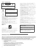
FRONT PANEL
1 2 3 4 5 6
1. Power on-off switch, master power control
2. Indicator LEDs: Power LED, red indicator light for main power on
Dual color LED: Red Standby-mute, Green Auto-on
3. Volume input level adjustment. This control is used for level matching of the subwoofer system to the main
loudspeakers. We recommend that you start with this control in about the 9-10 o’clock position as an initial setting
and use the level controls on the main equipment for fine adjustment of the overall speaker level.
4. Subwoofer low-pass crossover control adjustable is from 40-160 Hz. This control is active only with the rear panel
switch in the subwoofer position. This control should be adjusted to obtain the smoothest transition in sound between
the subwoofer and your main speaker system.
5. Phase switch is for amplifier output phase control. Outward position is 0º amplifier signal phase and inward position
is 180º inverted amplifier signal phase. Please experiment with this setting. The correct setting is that which yields
the fullest bass and smoothest blend of the subwoofer with your main speakers. This control is active in both the
Subwoofer and LFE switch setting positions on the rear panel.
6. Ventilation air intake grille. It is important that for the proper operation of this amplifier that this intake remain
unobstructed both in the installation and during operation. Blocking this air vent will cause the amplifier to over
heat and shut down. If proper airflow is not maintained the amplifier could be damaged
.
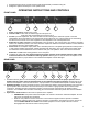
REAR PANEL
1 2 3 4 5 6 7 8
1. Ventilation exhaust grille is for thermostatically controlled fan. It is important that for the proper operation of this
amplifier that this intake remain unobstructed both in the installation and during operation. Blocking this air vent
will cause the amplifier to over heat and shut down. If proper airflow is not maintained the amplifier could be damaged.
2. SPEAKER OUTPUT connection terminals are of the 5-way binding post design, which accepts banana, pin or bare wire
type of speaker cable connections. We recommend that you use at least 14-gauge speaker wire for these hookup
connections. The black terminal is the speaker negative connection and the red terminal is the speaker positive
connection. For installation with the Phase Technology IW-100 and IW-200 subwoofers please refer to their installation
instructions.
3. Input selector mode switch sets the mode of operation of the amplifier.
• SUBWOOFER: This position allows the amplifier to be used as a full function subwoofer amplifier. All of the
features of the amplifier are operational.
• LFE: The LFE position is used for connection to home theater equipment with a separate controllable
subwoofer output that has its own crossover frequency compensation. This feature is found on most of the
current DOLBY DIGITAL® and DTS® home theater equipment. The front panel Crossover control is
disengaged when the selector switch is in this position.