
Instruction Manual

Completing the Installation
1. After the initial installation, be sure to check the pump operation by filling the
sump with water and observing the pump through one full cycle. When using the
dual float, the pump should run for 10 seconds after the float drops to its original
position.
2. Replace the pit cover making sure not to pinch or crimp the pump wire with the
cover. The pit cover either has a ‘hole punch’ that will allow the cord to be
passed through it, or a hole can be drilled in the cover.
Understanding the Warnings & Alarms
AC power is out
There are several causes for power
failure. The most common causes
are a power outage by the electric
company or a tripped circuit
breaker. Although the deluxe
controller can not run the pump, it
will sound an alarm indicating the
loss of power. This will allow the
homeowner to address the problem.
If this warning light and alarm are
on, the control box is not receiving
AC power for one of many reasons:
1. The control box is not plugged
in
2. The power to the house is out
3. The circuit breaker to that
outlet has been tripped
4. The ground fault interrupter on
that outlet has been tripped
5. A power brownout is taking
place
Power Failure Alarm slide switch
When the controller is not receiving
AC power, the monitoring features
and the audible alarms are powered
by the 9-volt battery. This type of
battery will power the controller for many hours, but not indefinitely. Once the
source of the AC power alarm is determined, it is suggested that the Power Failure
Alarm slide switch be turned to the OFF position until the power is restored. This
will preserve the battery and silence the alarm. When AC power is restored, slide this
switch back to the ON position.
Note: If the AC power is restored and the slide switch is in the OFF position, the alarm
and light for the 9-volt battery warning will activate, even if the battery is good. This
is a reminder to reset the alarm. Slide the switch to the ON position. If the battery is
good, the light will go out. If the alarm continues to sound, replace the battery.
The system is operating
This light should be ON and flashing at all times. It is included to indicate that the
system is monitoring the sump conditions. This light will not illuminate when:
1. The power is out and the Power Failure Alarm slide switch is in the OFF position
2. The power is out and the 9V battery is discharged
3. The controller is not functioning. Contact the Glentronics service department
The 9-volt battery is low
1. The 9-volt battery located in the top of the control box is coming to the end of
its useful life. Replace it with a new 9-volt alkaline battery.
2. The Power Failure Alarm switch is in the OFF position. It must be in the ON
position at all times, except when silencing an actual power failure condition.
Pump or float problem
This key feature monitors the time that the float switch is up continuously or in the
activated position. It is unusual for a pump run for 10 or more minutes continuously.
This can occur for many different reasons. Either the float is stuck in the up
position, there is a mechanical problem with the pump, or there is a problem with the
plumbing connections. Please refer to the Troubleshooting Guide on the back.
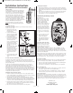
Dual Float Switch
The dual float switch contains two large floating rings
enclosed within a protective cage. Water will lift the
bottom float by a
1
⁄4⬙, which will activate the pump. If
for any reason the lower float does not activate the
pump, the water will rise and activate the second
switch. As the pump evacuates the water from the pit,
the floats will drop. The pump will run for an additional
10 seconds to evacuate the pit completely after the
float drops. The float switch wire includes a connector
that can be separated from the controller when the wire
needs to be threaded through small openings.
Note: When mounting the float switch, position the
bottom of the cage at the height you want the pump
to activate.
Installing the Dual Float
The PHCC Pro Series dual float switch is easy to install by using the enclosed
stainless steel hose clamp.
1. Hold the float switch to the
discharge pipe so the cage is
below the bracket.
2. Secure the float to the pipe
with the enclosed hose clamp,
but do not completely tighten
the clamp at this time.
3. Position the float switch to a
level where the bottom of the
float cage is no lower than 3⬙
above the bottom of the
pump. To avoid debris pouring
onto the float, it should be
positioned on the side of the
discharge pipe opposite the
drain tile.
Note: It is important to mount
the float below the drain tile
that empties into the pit.
Mounting it above the drain tile
would allow water to fill the
drain tile before the pump is
activated to pump out the
water.
4. Once the float switch is in the
desired position, tighten the
clamp.
The Deluxe Dual Float Controller Model # DFC2
The benefit of this controller is that it will sound an alarm when problems exist or
maintenance is needed. The controller will also run the pump once a week for
approximately four (4) seconds. This test will exercise the pump and help ensure the
pump is working properly.
The PHCC Pro Series Deluxe Dual Float Controller features a series of warnings
(audible and visual) that pinpoint potential problems with the pump, switch and
power conditions. The controller will sound an alarm when power has been
interrupted, when the pump has run for more than 10 minutes continuously, or when
the 9V battery is low. The 9V battery (sold separately) runs the controller during a
power outage, allowing it to sound an alarm if the circuit breaker trips, the controller
is not plugged in securely, or the home’s power is interrupted. Note: The 9V battery
will only power the switch, not the pump.
Installing the Deluxe Dual Float Controller
1. Mount the controller to the wall through the 4 holes on the cabinet using the
proper mounting hardware for the application. The controller should be mounted
at least 4⬘ from the floor and within 4’ of the outlet.
2. Open the plastic door on the top of the unit and using a flat head screwdriver
adjust the dial to select the number of seconds that the pump will run after the
float drops. The dial can be adjusted from 5-45 seconds. The manufacturer default
is about 10 seconds. Install a 9V alkaline battery and replace the plastic door.
3. Plug the control box into a properly grounded, 3-prong receptacle (preferably
with ground fault circuit interrupt). Then, plug the pump into the receptacle on
the control box. Do not use an extension cord.
4. Make sure the Power Failure Alarm slide switch is in the ON position.
Glentronics, Inc.
Lincolnshire, IL 60069
800-991-0466
www.stopflooding.com
1806069 (05/11)
Insta
l
l
a
ti
on
Instructi
ons
DFC2
Del
u
x
e Du
al
Fl
o
at Co
n
tr
o
l
l
er
Deluxe Dual Float inst_Deluxe Dual Float final 5/3/11 8:59 AM Page 1