Copyright Statement Feixun is the registered trademark of Shanghai Feixun Communication Co.,Ltd. Other trademark or trade name mentioned herein are the trademark or registered trademark of the company. Copyright of the whole product as integration, including its accessories and soft ware, belongs to Shanghai Feixun Communication Co.,Ltd. Without the permission of Shanghai Feixun Communication Co.,Ltd., individual or part y is not allowed to copy, plagiarize, imitate or translate it into other languages.
Table of Contents CONTENTS Introduction ………………………………………………………………………………… 1 Product Overview … … … … … … … … … … … … … … … … … … … … 1 Main Features … … … … … … … … … … … … … … … … … … … … … 3 Installation …………………………………………………………………………………… 5 Physical Connection … … … … … … … … … … … … … … … … … … … 5 Configure the Computers IP Address … … … … … … … … … … … … 5 Setup Wizard … … … … … … … … … … … … … … … … … … … … … … 8 Router Configuration …………………………………………………………………11 Basic Set ting … … … … … … … … … … … …
Table of Contents DHCP Service … … … … … … … … … … … … … … … … … … … … … … … … 23 Static Address Allocation … … … … … … … … … … … … … … … … … … … 24 DHCP Client List … … … … … … … … … … … … … … … … … … … … … … … 24 Forwarding Rule … … … … … … … … … … … … … … … … … … … … … … … … 24 Port Forwarding … … … … … … … … … … … … … … … … … … … … … … … 25 Port Triggering Set tings … … … … … … … … … … … … … … … … … … … … 25 DMZ Host ………………………………………………………………… 27 UPnP Set tings … … … … … … … … … … … … … …
Table of Contents System Log … … … … … … … … … … … … … … … … … … … … … … … … … 38 Traffic Statistics … … … … … … … … … … … … … … … … … … … … … … … 38 Setup Wizard … … … … … … … … … … … … … … … … … … … … … 39 Soft ware Upgrade Soft ware Update … … … … … … … … … … … … … … … … … … 39 …………………………………………………………… 39 Logout … … … … … … … … … … … … … … … … … … … … … … … 39 Specification ………………………………………………………………………………40 Appendix A: Troubleshooting ……………………………………………………41 Appendix B: Certi fication ……………………………………
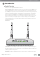
Chapter 1: Introduction Introduction Product Overview Thank you for choosing FWR-714N Wireless N Router. FWR-714N 300Mbps Wireless N Router is an all-in-one router, ideal for home and SOHO users to share broadband Internet connection over the wired and wireless net work. With the speed of up to 300Mbps, it can provide users with extraordinary smooth internet surfing, internet phone calling, on-line gaming, and HD video streaming.
Chapter 1: Introduction the Router sends or receives data over the wireless net work. Wi-Fi Protected Setup (WPS) LED: If you have client devices, such as wireless adapters, that support Wi-Fi Protected Setup, then you can use the Wi-Fi Protected Setup but ton to automatically configure wireless securit y for your wireless net work. To use Wi-Fi Protected Setup, refer to the section of Wi-Fi Protected Setup. WAN: The Internet LED lights up when there is a connection made through the Internet port.
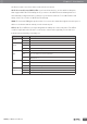
Chapter 1: Introduction Rear Panel ON/ OFF Power LAN 1~4 WAN WPS Reset Reset: Long press and hold the but ton for 8 seconds, the Router will reboot to its factory default set tings. WPS: Press the but ton and the WPS LED in front panel flashing, WPS function is enabled. WAN: Using an Ethernet cable (also called a net work or Internet cable), the Internet port connects the Router to your Internet connection, which is t ypically a cable or Digital Subscriber Line (DSL) modem.
Chapter 1: Introduction net work • QoS controls the reasonable allocation of bandwidth to achieve optimum utilization, ensuring reliable Internet connection • Quick wireless securit y setup by simply pressing the WPS but ton • WDS wireless bridge provides seamless bridging to expand your wireless net work • Built-in firewall featured with IP, MAC, URL filtering and ARP at tack prevention to protect your PC • Backward compatible with 802.
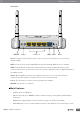
Chapter 2: Installation Installation Physical Connection Internet Power Socket Router ON/ OFFPWR 6 5 LAN4 LAN3 LAN2 LAN1 WAN WPS RST 4 3 Modem 2 1 PC Note: • Actual product may be different as the picture, but the installation will be the same. • Please use the included power adapter. Use of a different power adapter could cause damage and void the warrant y for this product. • Please ensure the Power, LAN and WAN lights are ON when the installation finished successfully.
Chapter 2: Installation 2. Select and double click Network Connection. 3. Right click Local Area Connection and then select Properties.
Chapter 2: Installation 4. Select Internet Protocol (TCP/IP) and click Properties. 5. Select Obtain an IP address automatically and Obtain DNS server address automatically. Then click OK . For Windows Vista/7 1. Click Start> Control Panel. 2.
Chapter 2: Installation (Change adapter settings for Windows 7). 3. Right click Local Area Connection and then click Properties. 4. Select Internet Protocol Version 4 (TCP/IPv4) and click Properties. 5. Select Obtain an IP address automatically and Obtain DNS server address automatically. Then click OK . Setup Wizard After successful installation, now you can go ahead with connecting to the internet, the operations are as following: 1. Open your web browser and enter 192.168.0.1. 2.
Chapter 2: Installation 4. You are prompted to select your WAN interface t ype, there are three t ypes available: DHCP, Static IP and PPPoE . a. Select Dynamic IP (DHCP) if your ISP does not give you any IP numbers to use. This option is commonly used for cable modem services. Router will obtain IP address information automatically. In this case, no need to input anything but click Next. b.
Chapter 2: Installation 5. In this page, please set the Wireless Net work Name (SSID), Mode, Wireless Securit y, click Next. 6. Click Finish, you would successfully access to the internet.
Chapter 3: Router Configuration Router Configuration You will see the five main menus on the left of the web -based utilit y. On the right, there are the corresponding explanations and instructions. The Status page provides the current status information about the Router. All information is read-only. Basic Setting The basic set ting section configures the Router to your Internet connection. Most of this information can be obtained through your Internet Service Provider (ISP).
Chapter 3: Router Configuration WAN Interface Connection Type: Dynamic IP: Obtain the IP address automatically assigned by the DHCP server from the ISP. Static IP: Have a static IP address provided by the ISP. PPPoE: Access the Internet by virtual ADSL dialup. L2TP: Layer 2 Tunneling Protocol (L2TP) is a service applies to connections in Israel only. PPTP: Point-to-Point Tunneling Protocol (PPTP) is a service applies to connections in Europe only.
Chapter 3: Router Configuration Wireless Status: If you do not have any other wireless devices in your net work, select Wireless Disabled. Wireless Network Name (SSID): The name of routers wireless net work. The wireless work station must keep the same SSID name with the APs for connections. By select Hidden or Isolated, the device can open or close to search available APs.
Chapter 3: Router Configuration supports to configure different securit y classes bet ween the main SSID and the subordinate SSID. Security Mode: There are several different securit y modes; you can choose one from disable, open, share, WEPAUTO, WPA-PSK WPA2-PSK, and WPA-PSK/ WPA2-PSK etc.. The operations of each securit y mode are as following: • Mode 1: Security Mode > Disable If you do not want to use wireless securit y, check this radio but ton.
Chapter 3: Router Configuration Network Settings There are five submenus under the Net work Set ting menu as shown below. Click any of them, and you will be able to configure the corresponding function. • Operating Mode This page is used to set the operating mode of the device. Please choose Bridge mode or router mode according to your requirement; When the NAT is enabled, it can provide the transfer of internal / external net works addresses for the LAN and wireless net works.
Chapter 3: Router Configuration • LAN Interface Settings MAC Address: The Routers physical MAC address as seen on your local net work, which is unchangeable. IP Address: The Routers LAN IP Address (not your PCs IP address). Once you modify the IP address, you need to remember it for the Web -based Utilit y login next time. 192.168.0.1 is the default value. Subnet Mask: It ’s shown the Routers subnet mask for measurement of the net work size. 255.255.255.0 is the default value.
Chapter 3: Router Configuration PPTP Server Basic Settings: Point-to-Point Tunneling Protocol (PPTP) allows the Pointto-Point Protocol (PPP) to be tunneled through an IP net work. To allow PPTP tunnels to pass through the Router, keep the default as Enabled. Force MPPE Encryption: Keep the default as Enabled. PPTP user: Enter PPTP username provided by your ISP. PPTP password: Enter PPTP password provided by your ISP. PPTP client IP: Enter the PPTP client IP address.
Chapter 3: Router Configuration from your computer and auto fill in the blanks. Save: Click the Save but ton to save your set ting. Wireless Settings There are seven submenus under the wireless menu. Click any of them, you will be able to configure the corresponding function. • Basic Settings Please refer to section of Basic setting > wireless setting. • Wireless Security Settings Please refer to section of Basic setting > Wireless Security Setting.
Chapter 3: Router Configuration 2. Fill MAC address 00:0A:EB:00:07:5F in and click Save. If you want MAC address (00:0A:EB:00:07:5F) cannot access the wireless net work while others can: 1. The securit y policy chooses to refuse. 2. Filling MAC address 00:0A:EB:00:07:5F in and click Save. In the MAC Address list, click Remove to delete the MAC addresses selected. • Advanced Wireless Settings This section is to configure the advanced wireless set ting of the Router, including the Radio Preamble, 802.
Chapter 3: Router Configuration in this field will be fragmented. Too many data packets will lower the wireless net work performance. The Fragment Threshold value should not be set too low. The default value is 2346. RTS Threshold: Set the RTS (Request to send threshold) threshold. When the packet size is larger than the preset RTS size, the wireless router will send a RTS to the destination station to start a negotiation. The default value is 2347.
Chapter 3: Router Configuration WPS (Wi-Fi Protected Setting): Easy and quick to establish the connection bet ween wireless net work client and Router through encrypted contents. The users only enter the PIN code to configure without selecting encryption method and entering secret keys by manual. WPS Mode: Supports t wo ways to configure WPS set tings: PBC (Push-But ton Configuration) and PIN code. PBC: Select the PBC but ton or press the WPS but ton on the panel of the Router.
Chapter 3: Router Configuration WDS Mode: In this mode, you can expand the scope of net work by combining up to four other access points together, and every access point can still accept wireless clients. Bridge Mode: You can wirelessly connect t wo or more wired net works via this mode. In this mode, you need to add the Wireless MAC address of the connecting device into the Routers AP MAC address table or select one from the scanning table.
Chapter 3: Router Configuration set ting. DHCP Server The TCP/ IP protocol set tings include the information of the IP address, subnet mask, gateway, and DNS server. Properly configuring the TCP/ IP protocol for all computers in the LAN is not easy. Fortunately, the DHCP server provides this function. • DHCP Service If you enable DHCP server of the router, the DHCP server automatically configures the TCP/ IP protocol for each computer in the LAN.
Chapter 3: Router Configuration • Static Address Allocation IP Address: Enter one IP address for the computer on the LAN net work. MAC Address: Enter the MAC address of the computer you want to assign the above IP address. Click Add to add the entry in the list. Save: Click the Save but ton to save your set ting. • DHCP Client List Refresh: Click to refresh the DHCP client list.
Chapter 3: Router Configuration • Port Forwarding Disable/Enable: To realize the function of port forwarding, select Enable. Rules Name: Enter the Rules Name. Server IP Address: Enter the IP address of the server that should receive these requests. Details please refer to the note below. Server Port Rang: The numbers of External Ports. You can t ype a service port or a range of service ports (in XXX – YYY format, XXX is the start port number, YYY is the end port number).
Chapter 3: Router Configuration Application Name: Describe the name of the application that being set. Start/End Trigger Port: The port for outgoing traffic. An outgoing connection using this port will trigger this rule. Trigger Protocol: The protocol used for Trigger Ports, TCP, UDP, or TCP/UDP. If you are not clear about which protocol was being used, TCP/UDP is recommended. Open Port: The port or port range used by the remote system when it responds to the outgoing request.
Chapter 3: Router Configuration Please select one of the applications: There are few common applications available such as Dailpad, MSN gaming, PC Phone etc. the blank will be automatically filled once been chosen. Custom application name: If the application you want to add is not included, enter the blank manually. Save: Click the Save but ton to save your set ting.
Chapter 3: Router Configuration • UPnP Settings UPnP: Click the checkbox to Enable or Disable the UPnP. Save: Click the Save but ton to save your set ting. • Multicast Forwarding Settings Security Options There are four submenus under the Securit y Options menu: Security Settings, Advanced Security Settings, LAN Web Management and Remote Web Management. Click any of them, and you will be able to configure the corresponding function.
Chapter 3: Router Configuration Stateful Packet Inspection (SPI): When the SPI firewall is enabled, the system refuses all requests from the Internet. Only packets that belong to connections that respond requests from the LAN and for which status database is created can pass the firewall and access to the LAN. By default, the SPI is enabled. To expose all hosts in the LAN to the Internet, you can disable SPI.
Chapter 3: Router Configuration Block the PING packets from the WAN interface: If you select this option, the PC in the WAN cannot send the PING packets to the router. Block the PING packets from the LAN: If you select this option, the PC in the LAN cannot send the PING packets to the WAN. Save: Click the Save but ton to save your set ting. • LAN Web Management The alternative to remote web management, it is to allow the net work administrator to manage the Router in LAN.
Chapter 3: Router Configuration Access Control There are t wo submenus under the Access Control menu. Click any of them, and you will be able to configure the corresponding function. • MAC/IP/Port Filter Settings This page is used to enable the firewall filtering function, select the filtering service or manually set the parameters that need to be filtered, such as MAC address, IP address and Port. You must set at least one filtering condition. You may also set multiple conditions or all the conditions.
Chapter 3: Router Configuration Web URL Filter: Check to enable URL filter. Save: Click the Save but ton to save your set ting. Routing Settings There are t wo submenus under the Routing Set ting menu. Click any of them, and you will be able to configure the corresponding function. • Static Routing Table The main dut y for router is to look for a best path for every data frame, and transfer this data frame to destination. So, it is essential for the router to choose the best path, i.e.
Chapter 3: Router Configuration IP Bandwidth Control There are t wo submenus under the IP Bandwidth Control menu. Click any of them, and you will be able to configure the corresponding function. • IP Bandwidth Control Settings Enable IP bandwidth control: If you select it, the bandwidth control rule takes effect. Total Uplink Bandwidth: The rate of uploading through the WAN interface. Total Downlink Bandwidth: The rate of downloading through the WAN interface.
Chapter 3: Router Configuration the master bandwidth. The max rate must > 0. If the max rate is larger than the master bandwidth, the rule will use master bandwidth instead. Save: Click the Save but ton to save your set ting. Dynamic DNS Settings The DDNS (Dynamic Domain Name System) is supported in this router. It is to assign a fixed host and domain name to a dynamic Internet IP address, which is used to monitor hosting website, FTP server and so on behind the Router.
Chapter 3: Router Configuration • Network Time Settings Current time: Show the current time. Time Zone: Select your time zone from the drop -down menu. Network time server: To set NTP server. Save: Click the Save but ton to save your set ting. Note: The system will Synchronous with the Net work Time Server every hour after saving, and it will affect the WAN dial-up on demand. • Diagnosis Tools Select: Select Ping or Tracert. IP Address/Domain Name: The destination IP address or domain name.
Chapter 3: Router Configuration out. Ping Timeout: The timeout time of the ping operation. Tracert Hops: The hops of tracert. Click Start Diagnosis but ton, the selected ping or tracert testing will be started. Below is a Ping diagnosis example that router has been connected to IP 172.16.160.31: Below is a Ping diagnosis example that router has failed to connect to IP 100.1.1.
Chapter 3: Router Configuration • Load Default Settings Load Default Settings: Click this but ton to restore to factory default set tings. User Name: admin Password: admin IP Address: 192.168.0.1 Subnet Mask: 255.255.255.0 Note: After restoring to default set tings, please restart the device, then the default set tings can go into effect. • Export and Load Settings • Reboot Rebooting the Router makes the set tings configured go into effect or to set the Router again if set ting failure happens.
Chapter 3: Router Configuration • System Settings Account: Enter the username you set. Enter the new Password: Enter the password you set. Re-enter password: Re-enter the password you set. • System Log The section is to view the system log. Click the Refresh to update the log. Click Clear to clear all the shown information. If the log is over 150 records, it will clear them automatically. Enable remote System Log: Check the radio but ton to enable remote System Log.
Chapter 3: Router Configuration Setup Wizard Please find the section of Setup Wizard. Software Upgrade Software Update You can choose to upgrade manually by: 1. Click the Browse but ton to browse the directory where you download the soft ware upgrade files. 2. Click Update but ton to start upgrade. Or you can choose to upgrade automatically by click the Update but ton, the router will download and upgrade automatically from FTP server. Router will auto reboot when the upgrade finished.
Chapter 4: Specification Specification Wireless Standard IEEE 802.11n, IEEE 802.11g, IEEE 802.11b, CSMA/ CA with ACK Wireless Signal Rate 11n: 300Mbps 11g: 54Mbps 11b: 11Mbps Frequency Range 2.4-2.
Appendix A: Troubleshooting Appendix A: Troubleshooting 1. Feixun Setup cannot find my Router. If Feixun Setup is not able to communicate with your Router during installation, please check the following items. • Ensure that the Router is on. The front-panel light should be on. • Make sure the computer is connected to the routers LAN port via cable. • Make sure the routers WAN port is connected to DSL modem via cable.
Appendix A: Troubleshooting • Search available net works and choose your net work. If your net work SSID is not listed in, please connect to Router via a net work cable, visit 192.168.0.1 and ensures the Broadcast SSID is enabled. This set ting can be found on the Wireless Set tings page. • Make sure the wireless net work name or SSID is the same on both the computer and the Router.
Appendix B: Certification Appendix B: Certification FCC Statement This equipment has been tested and found to comply with the limits for a Class B digital device, pursuant to part 15 of the FCC Rules. These limits are designed to provide reasonable protection against harmful interference in a residential installation.
Appendix B: Certification CE Mark Warning Marking with the above symbol indicates compliance with the Essential Requirements of the R&TTE Directive of the European Union (1999/5/ EC). This is a class B product. In a domestic environment, this product may cause radio interference, in which case the user may be required to take adequate measures.
Appendix C: Glossary Appendix C: Glossary • 802.11b: The 802.11b standard specifies a wireless net working at 11 Mbps using directsequence spread-spectrum (DSSS) technology and operating in the unlicensed radio spectrum at 2.4GHz, and WEP encryption for securit y. 802.11b net works are also referred to as Wi-Fi net works. • 802.
Appendix C: Glossary Ethernet Compatibilit y Alliance (WECA, see ht tp:// w w w.wi-fi.net), an industry standards group promoting interoperabilit y among 802.11b devices. • WLAN (Wireless Local Area Network): A group of computers and associated devices communicate with each other wirelessly, which net work serving users are limited in a local area.
Appendix D: Technical Support Appendix D: Technical Support Please contact Feixun technical support through Feixun website: www.feixun.com.cn Support via E-mail: support@feixun.com.cn Before you contact technical support, please have the following ready: • Model number of the product (e.g. FWR-714N) • Hardware version (e.g. Ver.: A1.0) • Serial number (S/ N) All these information can be found on the label at the bot tom of your product.
www.feixun.com.cn Shanghai Feixun Communication Co., Ltd.