
User's Manual

Product overview
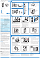
What’s in the sensor box Tools you may need
Step ladder
Drill
Pencil
Pliers
What’s in the switch box
Install the switch
black
brass
ground
white
red
load
120-277 V~
50 / 60 Hz
hot/live
neutral
Switch
WARNING: Wiring the device with power
ON could result in serious injury or death.
1 Remove power from the mains at fuse or circuit
breaker.
2 Remove the old switch, if needed.
3 Connect the wires according to the wiring diagram
above.
Note: Hot/live and neutral may not be swapped.
black
brass
ground
white
red
hot/live
neutral
120-277 V~
50 / 60 Hz
Three-way slave switch
4 For a three-way circuit connect the wires as
follows:
T • he master switch (that controls the load)
according to the regular wiring diagram.
The • slave switch (no load) according to the
wiring diagram above. Make sure that the switch
has a steady feed (hot/live and neutral).
The three-way configuration is done via the
menu, later in the installation.
PHILIPS
PHILIPS
Multigang wall box
break
PH
IL
IP
S
P
HI
L
IPS
P
H
ILI
P
S
PH
ILIP
S
5 If installing in a multigang wall box: break the tabs
of joining sides. Do not break the outside tabs on
controls at the end of the gang.
PHILIPS
6 Place the switch into the wall box, and fix it with the
mounting bolts.
7 Power the mains at fuse or circuit breaker.
P
H
I
L
I
P
S
ON
OFF
8 Test that the switch is wired correctly using the
rocker to turn the lights ON/OFF.
P
H
I
L
I
P
S
9 Attach a wall plate adapter and wall plate. Wall
plate and adapter must be purchased separately.
FCC and IC Regulations
This device complies with Part 15 of the FCC Rules and RSS-Gen of IC Rules.
Operation is subject to the following two conditions :
(1) this device may not cause harmful interference, and
(2) this device must accept any interference received, including interference that may cause
undesired operation.
FCC WARNING: Changes or modifications not expressly approved by Philips Lighting
Electronics N.A. could void the user’s authority to operate the equipment. This product is
intended for commercial use only.
Co-location : This transmitter must not be co-located or operated in
conjunction with any other antenna or transmitter.
CAUTION : Radio Frequency Radiation Exposure
This equipment complies with FCC radiation exposure limits set forth for
uncontrolled equipment and meets the FCC radio frequency (RF) Exposure
Guidelines in Supplement C to OET65. This equipment has very low levels of
RF energy that it deemed to comply without maximum permissive exposure
evaluation (MPE). But it is desirable that it should be installed and operated with
at least 20cm and more between the radiator and person’s body (excluding
extremities: hands, wrists, feet and ankles).
Copyright NOTICE
All referenced brands, product names, service names and trademarks are the property
of their respective owners. Copyright 2009 Koninklijke Philips Electronics N.V.
TECHNICAL SUPPORT
For technical support on this product, please contact:
Philips Lighting Electronics N.A.
10275 W. Higgins Road
Rosemont IL 60018
Customer Care: 1-800-372-3331
tech.service.rosemont@philips.com
PHILIPS
PHILIPS
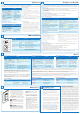
Sensor unit
Link button
Switch
Mounting frame
Side tabs
Wires
Retractable, rotatable
shield
Link button
”Traffic light”
indicator LEDs
Rocker
Menu button
Movement detector
Indicator LEDs
Mounting plate
Movement detector (”sensor”)
Wall switch (”switch”)
Screwdrivers
(small & large)
Install the sensor
301
1 Set the dial on the sensor to 1 minute for testing
purposes.
2 Place the battery into the sensor.
CAUTION: Only use a high-quality 3.6V lithium-
thionyl chloride battery with the sensor.
See SAFETY for more information on the battery.
23.6ft (7.2m)
17.7ft (5.4m)
17.7ft (5.4m)
11.8ft (3.6m)
h= 8ft (2.4m)
Large movements
Small movements
h
3 Choose the sensor location on the ceiling.
The window arrow in the mounting plate defines
the direction of the detection field, which is
rectangular. See Sensor placement guidelines for
more information.
Sensor placement guidelines
The sensor should be mounted in such a way that:•
� Small movements are detected for the workspace
� Large movements are detected for the entire room,
and in particular for the area near the doorway.
� Motion from adjectent areas, e.g. the hallway, is not
picked up.
The • center of a room is usually not a good location.
Moving the sensor towards the wall where the door is
located may still cover the entire room, while blocking
unwanted detection of motion from the hallway.
The sen• sor should not be placed close to heat
sources (especially incandescent lamps) or HVAC
exhausts.
4 Fix the mounting plate onto the sensor‘s location,
using the mounting hardware. Alternatively, use
toggle bolts (not included).
P
H
I
L
I
P
S
5 Place the sensor onto the mounting plate, and rotate
clockwise to fix.
6 If needed, pull out the sensor shield (indicated on the
ring with a dot), and rotate it to the required direction.
This step is covered in more detail in Configure, test
& finish.
PHILIPS
(1x)(1x)(1x)
+
_
(2x) (2x) (2x)
(4x)(1x)(1x)
PHILIPS
(2x)
1
2
3
4
EN
PHILIPS
PHILIPS
Install the switch
Install the sensor
Link devices
Configure, test & finish
Product description
OccuSwitch
TM
Wireless is a system for automatically controlling
the lights based on occupancy. The system uses two parts: a
ceiling-mounted sensor and a switch. The switch will turn the
lights on and off based on the information it wirelessly gets from
the battery-powered sensor.
Key figures
Sensor coverage area Will vary based on ceiling height
(up to 12ft).
For a typical height of 8ft (2.4m):
Large motion 17.7 x 23.6ft (5.40m x 7.20m)
Small motion 11.8 x 17.7ft (3.60m x 5.40m)
Larger areas will require multiple sensors.
Wireless range Switch - sensor: 50ft (17m)
Switch - switch (same plane): 18ft (6m)
Switch - switch (line of sight): 50ft (17m)
Maximum network size 10 Sensors/switches (any combination)
Operating voltage 120V AC or 277V AC, 60Hz
Load
rating:
Electronic
Fluorescent Ballast
120V / 10.8A / 1300VA
277V / 4.7A / 1300VA
Electromagnetic
Fluorescent Ballast
120V / 10.8A / 1300VA
277V / 4.7A / 1300VA
Incandescent lamps 120V / 6.67A / 800W
Motor load 120V / 0.25HP
Sensor dimensions
(diameter x height)
3.3 x 0.98 in (84 x 25mm)
Battery Lithium-thionyl chloride, AA 3.6V DC
Switch dimensions
(l x w x d)
4.13 x 2.56 x 1.79 in (105 x 65 x 45mm)
Minimum wall box depth 2.5 in
Operating conditions:
temperature
41°F - 104°F (5°C – 40°C)
Operating conditions:
humidity
20% – 85%, non-condensing
SAFETY
Parts of the switch carry mains power, which is a potential lethal
voltage. This product was designed and manufactured to ensure
maximum safety during operation and service. Always read these
safety instructions before installing, maintaining or servicing the
product, and strictly comply with these instructions.
General
- If you are unsure about any part of these installation
instructions, consult a qualified electrician.
- The devices are designed for indoor use only.
Do not expose the product to rain or moisture, to avoid short
circuit. Short circuit may cause fire or electric shock hazard.
Operate the devices between 41°F and 104°F (5°C and 40°C).
- Use only a soft damp cloth to clean devices, never use any
abrasive or chemical cleaner.
- Whenever it is suspected that safety protection is impaired,
the product must be made inoperative and secured against
unintended operation. The device must be serviced or
replaced as soon as possible. Safety is likely to be impaired
if, for example, the equipment fails to perform the intended
functions or if the equipment shows visible damage.
- Do not paint the devices.
Switch only
- Disconnect power at circuit breaker or fuse when servicing,
installing or removing the fixture of the switch.
- Use the switch only with copper or copper clad wire.
- Connect the switch to the power mains according to the
wiring scheme in this manual.
Sensor only
- The sensor cannot be used to control any load, without a
compatible switch.
- Use only high-quality 3.6V lithium-thionyl chloride batteries
with the sensor: one (1) Lithium-thionyl chloride (AA, 3.6V).
Using improperly rated batteries may damage the sensor.
- Dispose of used batteries promptly. Keep batteries away from
children, do not disassemble and do not dispose of in fire.
WARNING: This product must not be used to
control equipment that could create hazardous situations when
operated accidentally, like entrapment. Examples of equipment
that must not be controlled with this product include (but are
not limited to) motorized gates, garage doors, industrial doors,
(microwave) ovens, heating devices etc.
WARNING: It is the installer’s responsibility to
ensure that the equipment being controlled is visible from every
control location and that only suitable equipment is connected
to these controls. Failure to do so could result in serious injury
or death.
CAUTION: The battery used with the sensor device may
present a risk of fire or chemical burn if mistreated. Do not
recharge, disassemble, heat above 100°C, or incinerate. Replace
battery with Lithium-thionyl chloride (AA 3.6V) only.
Use of another battery may present a risk of fire or explosion.
OccuSwitch
TM
Wireless
Installation guide
PA-7200-R01 08-09
Installation steps: