
User's Manual

Maintenance
WARRANTY STATEMENT
The Philips OccuSwitch™ Wireless products, when properly installed and
under normal conditions of use (without overload, abuse or alteration),
is warranted to you, the original user, for a period of two (2) years from the
date of original purchase, to be free from defects in materials and workmanship.
If during the warranty period you believe the purchased product or any part
thereof has such a defect, you must return the product (or part) at your cost
during such period, with proof of purchase (or if installed by a third-party a
written explanation of installation transaction with proof of date), to Philips
Lighting Electronics N.A (1-800-372-3331 / www.philips.com/advance), for
repair or replacement (or to an authorized Philips Lighting Electronics N.A.
supplier which agrees in advance to handle the return and replacement
by factory authorization). If the product or part is found by Philips to have
been defective in material or workmanship it will be repaired or replaced
(as deemed necessary by Philips Lighting Electronics N.A.), and the replacement
will be returned to you free of charge. The original user is solely responsible
for any costs associated with removal and re-installation of the product
and shipping to Philips Lighting Electronics N.A. or its authorized supplier.
PHILIPS LIGHTING ELECTRONICS N.A LIMITS THE DURATION OF
THE IMPLIED WARRANTY OF MERCHANTABILITY WITH RESPECT TO
THE PRODUCT TO THE LIMITED WARRANTY PERIOD SET FORTH
ABOVE, AND OTHERWISE DISCLAIMS ALL IMPLIED WARANTIES WITH
RESPECT TO THE PRODUCT AND ITS PARTS. Some states disallow
certain limitations on implied warranties so you should consult your
state law if you have a question regarding this limitation and disclaimer.
Philips Lighting Electronics N.A disclaims any and all liability for incidental,
consequential, special or indirect damage arising out of any claimed breach
of warranty or otherwise. However, some states do not allow exclusion
or limitation of such damages, so this disclaimer may not apply to you.
The remedy provided in this Limited Warranty for defective products
is the user’s sole and exclusive remedy, subject to your state law.
Further, this Warranty gives the user specific legal rights, and the
user may also have other rights which may vary from state to state.
If you believe warranty claim is warranted, you may contact your
nearest authorized Philips Lighting Electronics N.A supplier.
If one does not exist in your area, please contact Philips Lighting Electronics
N.A Customer Care at 1-800-372-3331 or via e-mail at:
tech.service.rosemont@philips.com
Menus
Action menu on switch
Action Result
1. To enter the menu press and hold
MENU until the red LED starts to
blink.
The red LED starts to
blink once every 2 secs.
2. Briefly press MENU again to go
to the next item. Repeat until the
right menu item is selected (see table
below).
The red LED blinks
2 times for the 2
nd
option,
3 times for the 3
rd
option,
etc.
3. To activate the selected item briefly
press LINK.
The green LED
confirms activation.
Action menu on sensor
Action Result
1. To enter the menu press and hold
LINK until the red LED starts to
blink.
The red LED starts to
blink once every 2 secs.
2. Briefly press LINK again to go to
the next item. Repeat until the right
menu item is selected (see table
below).
The red LED blinks
2 times for the 2
nd
option,
3 times for the 3
rd
option,
etc.
3. To activate the selected item press
and hold LINK.
The green LED lights
up to indicate activation.
Show linked devices: Troubleshooting function to test which devices are part of a single network. When activated, each device in the network
blinks its green LED for 30 seconds. It may take up to 1 minute before the sensors start to blink, and only after having detected motion.
Test sensor coverage: Sensors blink their yellow LEDs when motion is detected. The test automatically ends after 10 minutes or can be
stopped on each sensor separately, by pressing the LINK button. It does not affect normal operation of the system.
Change channel: If devices are shown missing (the red LED is blinking continuously), the wireless link may be disturbed. In this case use a
channel change to resolve the problem. The network will use the new channel. The LEDs on the device will blink green while trying the channel
change. After completing, the device will light the green LED in case of success, or blink the red LED in case of failure.
Menu items on switch
Red LED Item
1 blink Exit menu
2 blinks Show linked devices
3 blinks Test sensor coverage
4 blinks Change channel
Menu items on sensor
Red LED Item
1 blink Exit menu
2 blinks Show linked devices
3 blinks Test sensor coverage
Configuration menu on switch
Action Result
1. To enter the menu briefly press
MENU on a switch.
The yellow LED starts to blink once
every 2 secs.
2. Briefly press MENU again to go
to the next option. Repeat until the
right menu option is selected (see
table below).
The yellow LED blinks
2 times for the 2
nd
option, 3 times for the
3
rd
option, etc.
3. To activate the selected option:
Briefly press • LINK to activate
option A.
Press and hold • LINK to activate
option B.
The • green LED turns on to
indicate activation of option A.
The • green LED blinks to indicate
activation of option B.
Manual ON / Auto ON: By default, the lights will automatically turn on if
occupancy is detected. It is possible to disable this function: the system then requires
manual use of the rocker to turn on the lights. Using Manual ON makes the system
compliant to California Title 24 regulations.
Three-way / Stand-alone switch: By default the switch will act as a stand-alone
switch: the rocker only controls the load that is connected to that switch. However,
all switches react to all sensors. When configured as a three-way switch, all loads
are controlled from any switch.
Options on switch
Yellow LED Option A Option B (default)
1 blink Exit menu Exit menu
2 blinks Manual ON/Auto OFF Auto ON/Auto OFF
3 blinks Three-way switch Stand-alone switch
PH
IL
IP
S
Troubleshooting
The lights turn off too quickly
The system has a smart timer that adjust the switch off time
automatically. If this is not sufficient, correct the sensor’s
movement timeout: set the dial to a higher value.
The system is set to Manual ON, but lights turn on
automatically
When entering the area within 5 minutes after lights turning
off, the system assumes that turning off was not desired.
The system shows that a linked device is missing
When a device is missing, use the menu to show all linked
devices. If a sensor does not show as linked, replace its
battery. If this does not resolve the error, reset all devices
(see below) and link them again (see Link devices).
The lights immediately turn on after being turned off
The sensor may be placed too close to a (heat generating)
light source. Move the sensor to a better location.
Reset the device to factory defaults
To reset the device to its factory default configuration:
Press and hold the link button on the device for
more than 10 seconds. Release the button when the
red, yellow and green LEDs light briefly.
LEDs and buttons
Indication Meaning
Red, yellow, green Device starts up
Blinking green For 10 seconds A device asked to show all linked devices
For longer Device is in linking mode
Blinking yellow Irregular Sensor is showing coverage
Every 2 seconds Device is in the configuration menu
Blinking red Regular A linked device is missing (see Troubleshooting)
Every 2 seconds Device is in the action menu
Steady yellow Lights are switched manually. Automatic
behavior resumes after vacancy
LINK
LINK
Shield
Red
Yellow
Green
Red
Yellow
Green
MENU
Sensor
Switch
Configure devices
When all sensors and switches are linked, it is a good time to change any settings. You can do this at any switch; the
settings are automatically sent to all devices in the network. You can select the following options in the configuration
menu (see Menus):
Manual ON/Auto OFF • (”Title 24 Vacancy Mode”): After activation, the lights turn off to indicate they need to be
switched on manually. In this mode the yellow LED (manual override) is not used.
Three-way switch • : After activation, test all switches by pressing their rocker. All switches should control all
connected loads.
Test sensor coverage
Once all devices are installed, linked and configured, you can test the installation to ensure that:
The sensor detects motion in the workspace. •
The sensor does not pick up motion from adjacent areas, e.g. the hallway. •
To test, take the following steps:
Troubleshooting
If the sensor’s coverage is not good enough,
you have the following options:
The sensor has a rectangular field of view. •
Rotate the mounting plate 90 degrees
if needed (see Install the sensor).
Move the sensor(s) to a better location.•
Add an additional sensor to enlarge the •
coverage area.
If the sensor(s) pick up motion when they should not, you have the
following options:
Move the sensor(s) to a better location. Moving it closer to the •
wall where the door is located may reduce unwanted detection
of hallway motion.
With your fingernails or a small screwdriver, (partly) retract the •
sensor shield. Rotate the shield in such way that it prevents the
unwanted motion detection.
Rotate the mounting plate to change the sensor’s field of view.•
Finish installation
Set the dial at the back of all sensors, to set the time delay after which the lights turn off when the workspace is
unoccupied. Some guidelines:
Shared rooms (such as copy rooms, coffee rooms, etc.) typically have lots of motion. •
The timer can be set to a small value, such as 5 or 10 minutes.
Private offices may have people sitting behind their desk typing for some time. •
A suitable timer value could be 15 minutes or longer.
Tip: After this initial setting, the timer is automatically extended by the sensor to adjust to the users’ occupancy pattern.
Congratulations, you have successfully installed the OccuSwitch™ Wireless system!
Configure, test & finish
Action Check
1. Ask other people to leave the room. You are the only person in the room.
2. Select Test sensor coverage from the action
menu on one of the switches (see Menus) and wait
up to 1 minute until the yellow LED on the
sensor starts to blink.
During the coverage test, the yellow LED on the
sensor blinks when movement is detected. This test ends
automatically after 10 minutes and does not affect normal
operation of the system.
3. Move around the room, testing corners and the
main workspace areas around the desks and tables.
Check that the yellow LED on the sensor blinks at all
(important) places.
4. Leave the room and walk by the hallway. Check that the yellow LED on the sensor does not blink.
5. Enter the room again. Check that the yellow LED on the sensor blinks.
6. Leave the room and wait for about 1 minute for
the lights to turn off, and then walk by the hallway.
Check that the lights do not turn on.
7. Enter the room. Check that the lights turn on when you pass the doorway.
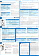
Link devices
Create a network
A combination of one or more switches and sensors that work together is called a network.
A network is created by linking one or more devices to a switch. Take the following steps to link one sensor to one switch:
Action Result
1. Tip: If the lights are on, use the
rocker to turn the lights off.
The lights turn off.
2. Briefly press the LINK button
on the switch (see picture below)
to enter the linking mode.
The green LED
on the switch starts
blinking.
3. Briefly press the LINK button
on the sensor to add it to the
network.
The lights turn on and
the green LED on
the sensor turns on.
4. Briefly press the LINK button
on the switch again to exit the
linking mode.
The green LED
on the switch stops
blinking.
Troubleshooting
If you cannot find a button or an LED, look below at •
LEDs and buttons.
In step 3, if the • red LED on the sensor turns on,
then linking failed. Try again. If the problem persists, see
if you can move the sensor closer to the switch. Keep in
mind the maximum distance between switch and sensor
(see Key figures).
In step 3, if the • red LED on the sensor starts to
blink, then you probably pressed and held the LINK
button, instead of pressing it briefly. The sensor entered
the action menu. Press and hold the link button to exit
(see also Menus). Then continue linking.
Link additional devices
Additional devices can be linked in a similar way:
Troubleshooting
If the • green LED starts blinking on any additional
switch, that switch is now also in linking mode, starting
its own network. Press the LINK button on that switch
and try the whole procedure again. If the problem
persists, the distance between the new switch and the
existing switch may be too large (see Key figures).
If the • yellow LED is turned on after linking, the
switch is in manual override and does not respond to
messages from the sensor. After you leave the room and
the sensor timer has expired, it will return to automatic
mode and the LED will be switched off.
Action Result
1. Make sure that the switch
that was initially used to setup
the network is in linking mode by
briefly pressing its LINK button.
The green LED is
blinking.
2. Link each additional switch
or sensor by briefly pressing its
LINK button.
The green LED on
the added switch/sensor
will turn on.
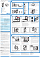
Routine lamp replacement
To safely do a routine replacement of a
connected lamp, the lamp must be physically
disconnected from mains power. To do so:
On all switches, firmly press the OFF-side •
until the rocker clicks into the position
where a yellow band with “OFF”
becomes visible.
The load is now separated from the mains by
an air gap, so you can safely replace the lamp.
WARNING: If this air gap function
is not used, the power to the load may be
switched on unintentionally while replacing
the lamp.
This could result in serious injury or death.
WARNING: For any procedure
other than lamp replacement, power must
be disconnected at the main electric panel.
Working on any such procedure with power
ON can result in serious injury or death.
Replacing the sensor battery
CAUTION: You must have read the
SAFETY section before replacing the
battery.
To replace the battery of the sensor:
1 Rotate the sensor counterclockwise to
remove it from the mounting plate.
2 In a safe and dry place, remove the old
battery and insert the new battery.
CAUTION: Use only high-quality
AA 3.6 V DC lithium-thionyl chloride
batteries with the sensor.
Using improperly rated batteries may
damage the sensor.
3 Place the sensor back on the mounting
plate and rotate clockwise to fix it.
4 Dispose of used battery promptly. Keep
away from children. Do not disassemble
and do not dispose of in fire.