
User's Manual

PHILIPS
PHILIPS
black
brass
ground
white
red
load
120-277 V~
50 / 60 Hz
hot/live
neutral
black
brass
ground
white
red
hot/live
neutral
120-277 V~
50 / 60 Hz
y
(4x)(1x)(1x)
PHILIPS
(2x)
P
H
I
L
I
P
S
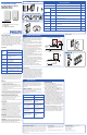
Installation Guide
OccuSwitch Wireless System
LRM172100 Switch
LRM173000 Dimmer
WARNING:WiringthewalldevicewithpowerONis
unsafeandcouldresultinseriousinjuryordeath.Turn
Offpoweratthecircuitbreakerbeforeinstallingthe
SwitchesandDimmers.
1 SwitchOfflinevoltageatcircuitbreaker.Wiring
HOTmaydamagetheelectronicandvoidthewar‐
ranty.
2 Rem
ovetheold
SwitchandinstallnewOccuSwitch
DimmerorSwitchfollowingthewiringdiagram.
Note:doNOTswapHot/liveandneutral.
3 Wirelessremote(3‐way)deviceswireasfollows:
Themasterdimmer(thatcontrolstheload)accord‐
ingtotheregularwiringdiagram.
Wiretheremoteswitch/dimmer(noload)acco
rd‐
ingto
thewiringdiagram.
Remote(3‐waygrouping)configurationisamenu
option,seeConfigurationinstruction(Yellow#2)on
backpage.
4 Toinstallinmulti‐gangwallback‐box,breakthe
tabsofjoiningsides.Donotbreaktheoutsidetabs
ondevicesattheendofthegang.Upto3de
vices
canbe
gangedinonethree‐gangbox.
5 Placethedimmerintothewallback‐box,andse‐
curewiththemountingscrews.
6 Powerthecircuitatfuseorcircuitbreaker.
7 CheckoperationON/OFForFadeUp/DimDown.
InstallationSteps
1. Installwalldevice
2. Installsensor(separateinstructions)
3. Linkdevices
4. Configure,testandfinish
ProductDescription
OccuSwitch™Wirelessautomaticallycontrolsthelights
basedonoccupancyanddaylight.Thesystemhastwo
parts:ceiling‐mountedsensorandwallmountpower
handlingdevice(switchordimmer). Theswitchwillturn
thelightsOnandOffbasedontheinformationreceived
fromthewirelessoccupancysensor.Thedimmerwill
dimlightsUpandDowntotheapp
ropriate
intensity
baseontheavailabledaylightinthespace.Thedimmer
canalsomanuallydimthelights.
Keyfigures
SAFETY
Partsoftheswitch&dimmercarrylinepower,whichisapoten‐
tiallethalvoltage.Thisproductwasdesignedandmanufactured
toensuremaximumsafetyduringoperationandservice.Always
readthesesafetyinstructionsbeforeinstalling,maintainingor
servicingtheproduct,andstrictlycomplywiththeseinstruc‐
tions.
General
‐Ifyouareunsureaboutanypartoftheseinstallationinstruc‐
tions,consultaqualifiedelectrician.
‐Thedevicesaredesignedforindooruseonly.
‐Toavoidshortcircuits,donotexposethisproducttorainor
condensingmoisture.Shortcircuitmaycausefireorelectric
shockhazard.Operatethedevicesbetween41°Fand104°
F
(5°Cand40°C)ambienttemperature..
‐Useonlyasoftdampclothtoclean,neveruseanyabrasiveor
chemicalcleaner.
‐Wheneveritissuspectedthatanunsafeconditionexists,
switchoffpoweratthecircuitbreakerandreplacethedevice.
Safetyislikelytobei
mpairedif,forexample,the
equipment
failstoperformtheintendedfunctionsoriftheequipment
showsvisibledamage.Donotpaintthedevices.
WallDevice(Switch&Dimmer)only
‐Disconnectpoweratcircuitbreakerorfusewhenservicing,
installingorremovingthefixtureoftheswitch.
‐Onlyusewithcopperorcoppercladwire.
‐Wireswitchtothelinepoweraccordingtothewiringscheme
inthismanual.
Sensoronly
‐Thesensorcannotcontrolloadsdirectlyusecompatibleswitch
ordimmer.
‐Useonlyhigh‐quality,AAsize,3.6Vlithium‐thionylchloride
batterieswiththesensor.Usingimproperlyratedbatteries
maydamagethesensororfailtooperateproperly.
‐Disposeofusedbatteriespromptly.Keepbatteriesawayfrom
children,donotd
isassembleanddonotdi
sposeofinfire.
WARNING:Theproductisintendedtocontrollighting
loadsonly.DoNOTusetocontrolequipmentthatcouldcreate
hazardoussituations,likeentrapment.Forexamples,doNOT
installthisproducttocontrolmotorizedgates,garagedoors,
industrialdoors,microwaveovens,heatingdevices,etc.
WARNING:Itistheinstaller’sresponsibilitytoensurethat
theequipmentbeingcontrolledisvisiblefromeverycontrol
locationandthatonlysuitableequipmentisconnectedtothese
controls.Failuretodosocouldresultinseriousinjuryordeath.
CAUTION:Thebatteryusedwiththesensordevicemay
presentariskoffireorchemicalburnifmistreated.Donot
recharge,disassemble,heatabove100°C,orincinerate.Replace
batterywithLithium‐thionylchloride(AA3.6V)only.
Useofanotherbatterymaypresentariskoffireorexplosion.
800VA@120VAC(Mark10orequal)
1600VA@277VAC(Mark10orequal)
800W@120VAC(Incandescent)
Notrecommendedbutitworks
Dimmer
NOT
ratedfor:
ElectroMagneticFluorescent
MotorLoads
Switch
Load
Rating
1300VA@120or277VAC
0.25HP@120Vac
Switchoutputonly
Network
Size
16Sensors,Switches&Dimmers.
Wireless
Range
Wal
ldevice
tosensor:50ft(17m)
Walldevices(sameplane)18ft(6m)
Walldevices(lineofsight)50ft(17m)
Dimen‐
sions‐
4.13”x2.56”inx1.79”(105x65x
45mm)Singlegangwallmount.2.5”d
Dimmer
Load
Ratings
Environ‐
mental
Temp:40°Fto104°F(5°Cto40°C)
Humidity:20%to85%,noncond ensing
WallDeviceboxcontents
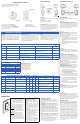
Indication Meaning Device
Red,Yellow,Green Devicestartsuporresettofactorydefaults All
Green
10sec. Adeviceaskedtoshowalllinkeddevices All
1Min. Deviceisinlinkingmode
Switch
Dimmer
Yellow
Blink
Irregular Sensorisshowingcoverage Sensor
Yellow
Blink
Every2
Sec.
Deviceisintheco
nfigurationmenu
Switch
Dimmer
RedBlink Regular
Alinkeddeviceismissing
(seeTroubleshooting)
Switch
Dimmer
RedBlink 2Sec.rate DeviceisintheActionmenu All
Steady
Yellow
AlwaysON
Lightsareswitchedmanually.Automaticmodereturnsafter
vacancytimeout.
Switch
Dimmer
RedBlink 5SecRate SensorB
atteryLo
w
Switch
Dimmer
RedBlink 2Sec.Rate Duringlinktest=lowbattery Sensor
LEDandButtons
1 INSTALLWALLDEVICE
Note:Afterwalldeviceisinstalledandpowerisre‐
turned,testallwalldevicesbypressingtherocker
switchON/OFF.Allswitches/dimmersshouldcontrol
connectedloads.Iftheydonotcontrolthelights
checkwiring.
Createanetwork:Tocreateawirelessnet‐
workbycombinationofupto16switches,dimmers
andsensorstakethefollowingsteps.
HINT:topreventcross‐linkingroomsonlyoneperson
shoulddothelinks.
3 LINKDEVICES
Troubleshooting
SeeLEDsandbuttonsdescription.
Whenlinking,ifRedLEDonthesensorturnsOn,
thenlinkingfailed.Tryagainandmovethesensor
closertotheswitch,(within50ft.)
Whenlinking,ifRedLEDonthesensorstartsto
blink,youpressedandheldtheLINKbuttontoo
long.Thesensoren
ter
edtheACTIONmenu.Press
andholdthelinkbuttontoexit.
Warning:IfthegreenLEDstartsblinkingonanother
switch/dimmer,thatswitch/dimmerisnowalsoin
linkingmode,startingitsownnetwork.Pressthe
LINKbuttononthatswitch/dimmerandtrythe
wholeprocedureagain.Iftheproble
mpe
rsists,the
distancebetweenthenewswitch/dimmerandthe
existingswitchmaybetoolarge(seeKeyfigures).
Note:IftheyellowLEDisturnedONafterlinking,the
switch/dimmerisinmanualoverride.Afterthesensor
timerhasexpired,itwillreturntoautomaticmodeand
theLEDwillgooff.Or,holddowntheONro
cker
until
theyellowLEDgoesout,returningtoautomode.
RESETtofactorydefaultsettings‐Ifthelinksorset‐up
isnotcorrecttheycanbeclearedineachdeviceby
holdingdowntheLINK/ACTIONButtonforabout10
seconds.Rel
easewhen
LED’sbrieflyblinkalltogether.
AfterreleasingtheystepRED‐YELLOW‐GREEN.
ACTION RESULTS
TestOn/OffandsettoOff Lightsturnoff.
1.BrieflypresstheLINK
button(Topofswitch/
dimmer)forlinkingmode.
GreenLEDonthe
switch/dimmerstarts
blinking.
2.BrieflypresstheLINK
buttononthesen
sor
toadd
ittothenetwork.
LightsturnOnand
sensor’sgreen LED
turnson.
3.BrieflypresstheLINK
buttononadditionaldevices
toaddtonetwork.
GreenLEDoneach
deviceturnsOnto
confirmlink.
4.BrieflypresstheLINK
buttononfirstswitch/
dimme
r
againtoexit.
GreenLEDonthe
switch/dimmerstops
blinking.
FCCCOMPLIANCESTATEMENT
This devicecomplies withpart15 oftheFCC rules. Operation is subject
to the following two conditions: (1) This device may not cause harmful
interference,and(2)thisdevicemust acceptany interference received,
includinginterferencethatmaycauseundesiredoperation.Anychanges
ormodifications not expresslyapproved byPhilipsco
uldvoidthe user
’s
authority to operate this equipment. This product is intended for com‐
mercialuseonly.
CopyrightNOTICE
All referenced brands, product names, service
names and trademarks are the property of their
respectiveowners.
Copyright2011KoninklijkePhilipsElectronicsN.V.
TECHNICALSUPPORT
Fortechnicalsupportonthisproductcontact:
PhilipsLightingElectronicsN.A.
10275W.HigginsRoad
RosemontIL60018
CustomerCare:1‐800‐372‐3331
tech.service.rosemont@philips.com
Mountingdetails
NeutralRequired
Bothwalldevice(switch&Dimmer)requireaneutral.
Theneutralcircuitdesignprovidesamorestableand
predictableelectricalsource.Themostcommonno‐
neutraldesigntricklesthereturnpowerthatoperates
communicationcircuitsinthewalldevicebackthrough
thelightingload(ballast).Thismethodhastoomany
unc
ertainties
tobe100%reliable.Aswemovefor‐
wardwiththisproductnewtechnologiesmayallowus
tochangetheneutralrequirement.
Switch&DimmerWiringDiagram
RemoteDeviceWiringDiagram
WallDevices&CeilingSensor
Toolsrequired(forentireinstall)