
User's Manual

SET-UP OPTIONS
For best result set each desirable option in the order
listed below.
WARRANTY STATEMENT
The Philips OccuSwitch™ Wireless products, when properly
installed and under normal conditions of use (without over-
load, abuse or alteration), is warranted to you, the original
user, for a period of two (2) years from the date of original
purchase, to be free from defects in materials and workman-
ship. If during the warranty period you believe the purchased
product or any part thereof has such a defect, you must return
the product (or part) at your cost during such period, with
proof of purchase (or if installed by a third party a written
explanation of installation transaction with proof of date), to
Philips Lighting Electronics N.A (1-800-372-3331 /
www.philips.com/advance), for repair or replacement (or to an
authorized Philips Lighting Electronics N.A. supplier which
agrees in advance to handle the return and replacement by
factory authorization). If the product or part is found by Philips
to have been defective in material or workmanship it will be
repaired or replaced (as deemed necessary by Philips Lighting
Electronics N.A.), and the replacement will be returned to you
free of charge. The original user is solely responsible for any
costs associated with removal and re-installation of the prod-
uct and shipping to Philips Lighting Electronics N.A. or its
authorized supplier.
Troubleshooting System
The lights turn off too quickly: The system has a
smart timer that adjust the off delay time automati-
cally. To change, set sensor’s minimum timeout dial to
a higher value.
The system is set to Manual ON, but lights turn on
automatically: When entering the area within 5 min-
utes after lights turning off, the system assumes that
turning off was undesired and turn ON the lights.
The system shows that a linked device is missing:
When a device is missing, use the ACTION #1 menu to
show all linked devices. If a sensor does not show as
linked, its battery may need to be replaced. If this does
not resolve the error, reset all devices and link them
again.
The lights immediately turn ON after being turned off
The sensor may be placed too close to a (heat generat-
ing) light source. Move the sensor to a better location.
Reset the device to factory defaults
To reset the device to its factory default configuration:
Press and hold the link button on the device for
more than 10 seconds. Release the button when the
red, yellow and green LEDs light briefly.
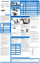
Maintenance
Routine lamp replacement
To safely do a routine lamp replacement,
on all switches, firmly press the OFF-side
until the rocker clicks into the position
where a yellow band with “OFF” becomes
visible.
The load is now temporarily separated
from the line voltage by an air gap switch,
so you can safely replace the lamp.
WARNING: If the air gap function is not
used, the power may be switched ON
unintentionally by the sensor while replac-
ing the lamp. This could result in serious
injury or death.
WARNING: For any procedure other
than lamp replacement, power must be
disconnected at the main electric panel.
Use approved LOCK-OUT/TAG-OUT proce-
dures to insure that the circuit is not acti-
vated accidently. Working with power ON
is unsafe and can result in serious injury or
death.
Replacing the sensor battery
CAUTION: You must have read the
SAFETY section before replacing the
battery.
To replace the battery of the sensor:
1. Rotate the sensor counterclockwise
to remove from mounting plate.
2. In a safe and dry place, remove the
old battery and insert the new
battery.
CAUTION: Use only high-quality AA
size 3.6 V DC lithium-thionyl chlo-
ride batteries with the sensor.
Using improperly rated batteries
may damage the sensor.
3. Place the sensor back on the
mounting plate and rotate clock-
wise to fix it.
4. Dispose of used battery properly.
DO NOT throw in trash. Keep away
from children. Do not disassemble
and do not dispose of in fire.
4 CONFIGURE, TEST & FINISH
Configure
When all sensors and wall devices are linked, you can
change the operation settings. This is done at any wall
device; the settings are automatically sent to the other
devices in the rooms network. You can select the fol-
lowing options in the Configuration and Action menus.
(Config #4)
Set High End Level - If you want to limit the maxi-
mum output from a dimmer set the desired high end
level and run through Configuration Menu (Yellow) #4.
After successfully installing and linking the sensors and
wall devices you can change settings to customize the
system to the needs of the user.
Configuration and set-up
To dim up, press and hold the ON button
To dim down , press and hold the OFF button
Menu operations use CONFIG and LINK/ACTION but-
tons as described in the Configuration (YELLOW) and
Action/RED menus below.
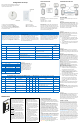
CONFIGURATION (Yellow) Menu for both Wall Devices - Press CONFIG button (Long to enter) (Short for next item)
Item Description Action
Store
Setting Indicator
Start Yellow Spike (…/…) Exist Long Press CONFIG to exit N/A
1 Yellow Blinks (…1…) Manual ON/ Auto OFF (Title 24)
Long CONFIG = Manual ON
Long ACTION = Auto ON
Automatic
2 Yellow Blinks (…1..1…) Multi-Way Configuration Long CONFIG to create multi-way group Long CONFIG
3 Yellow Blinks (…1..1..1…)
Dimmer Response Curve
(Dimmer Only)
Long CONFIG to change response curve Long CONFIG
4 Yellow Blinks (…1..1..1..1…)
Set High End Level (Task Tuning)
(Dimmer Only)
Long CONFIG = Sets maximum dim level
Long ACTION = Return to 100%
Automatic
ACTION (Red) Menu for Sensors and Wall Devices- Press LINK/ACTION button (Long to enter) (Short for next item)
Item Indicator Description
Wall
Switch
Wall
Dimmer
Multi-
Sensor
Occ.
Sensor Action Results
Start Red Spike (…/…) Exit X X X X Long LINK/ACTION to exit
1 Red Blinks (…1…) Show Linked Device X X X X Long LINK/ACTION to start
Automatic
2 Red Blinks (…1..1…) Test Sensor Coverage X X X X
Long LINK/ACTION to Start
Short LINK/ACTION on sensor to Finish
3 Red Blinks (…1..1..1…)
Calibrate Daylight dimming
set-point (< 1 min. process)
N/A X X X Long LINK/ACTION to Start Automatic
4 Red Blinks (…1..1..1..1…) Daylight Hold Back X N/A X X Long LINK/ACTION to Start
Automatic
5 Red Blinks (…1..1..1..1..1…) Channel Change X X X X Long LINK/ACTION to Start Automatic
SET-UP hint
Use a small screw drive or similar device to push the
Menu buttons.
Short button press : < 1 second
Long button press: > 2 seconds
Test sensor coverage
Once all devices are installed, linked and configured,
you can test the installation to ensure that:
The sensor detects motion in the workspace. Test to
make sure sensor does not pick up motion from adja-
cent areas, e.g. the hallway. This can be done at any-
time, see ACTION Menu for steps.
(Config #2)
Multi-Way Configuration - Several switches and
dimmers can be put in a group that control each oth-
ers load when operated manually.
You can create several independent control groups
linked to the ceiling sensors.
1. Use CONFIG menu item 2 - All wall devices will
start to blink: GREEN is included, RED is excluded.
2. Tap the ON button to include, OFF bottom, to
exclude.
3. Long CONFIG button press will save the settings.
4. Repeat from step 1 on different wall devices to
form more groups.
(Config #3)
Dimmer Response Curve - If
the Daylight dimming response
is too aggressive the Dimmer
can be set to respond less to
daylight. If the response is too
low the dimmer can be set to
react more to additional day-
light.
Dimmer Response Curve
1
Blink - Top LED
-50%
2
Blink - 2nd LED
-20%
3
Blink - 3rd LED
-10%
4
Blink - 4th LED (default)
Straight Line
5
Blink - 5th LED
+10%
6
Blink - 6th LED
+20%
7
Blink - Bottom LED
+50%
(Action #3)
Daylight Calibration (FIRST TIME) - Only one
sensor can be linked to one Switch (Hold-back) or one
Dimmer (continuous dimming) for Daylight Regulation.
The first time the daylight Action Menu is activate the
system unlocks and links the senor to the wall device
for Daylight regulation. This can be done from the floor
before mounting the sensor.
Next time - After the first activation and calibration
the daylight menu can be run from the wall device to
recalibrate the daylight settings.
Calibration process - When the sensor and the wall
device enter calibration mode the
Tip: It is important that the daylight is constant and is
not too bright (no need to calibrate in the dark).
1. Use dimmer to dim to the required light level
using light meter on the work surface.
2. Go into action menu on the sensor to select
Calibration daylight regulation set-point menu
item. (Yellow LED starts Blinking)
3. Clear the area under the light sensor (walk away).
4. Automatic Configuration will start in about a
minute. All dimmers in the system go to 100%,
then switch off. The green LED on the device
turns on. Sensor confirms new setpoint using
green LED. The system enters automatic light
regulation mode.
Note: This process can be repeated anytime after the
first time from the wall device without touching the
(Config #1)
Manual ON / AUTO OFF (Title 24 mode) - This is
a popular setting for maximum energy savings. It force
the occupant to manual activate the lights when they
enter the space and automatically turn OFF the light
when they leave. This save energy by keep the lights
OFF until they are actually needed.
Finish
OccuSwitch Sensors and Wall Devices do not need any
regular maintenance. You may find as people change
space and future is re-arranged that you need to re-
calibrate the daylight functions. This can easily be
done at floor level from the wall device.
(Action #5)
Channel Changing - In some building environments
the radio signal used for OccuSwitch Wireless may
encounter interference from another radio device.
Channel changing activate the system automatic radio
analysis function toe reset the channel. Use this func-
tion if you are having communications issues.
Manual Mode - Manual mode is entered when the
rock switch is pressed and the Yellow LED comes On.
After sensors are linked, the system will return to auto
mode when the room if vacant and the delay timer
expire. To return to Auto Mode Hold down the On
rocker until the Yellow LED goes out.
One to One SET-UP Combined Device SET-UP
LED response Signals
Spike - Very short blinks
Blink - LED switching On and Off
(Action #4)
Daylight Hold-Back - Similar to Daylight calibration
but results is to set the level at which the light will not
turn ON automatically (Hold-Back level)