Philips ‘TL’5 lamps To the reader This publication is based on the available product range and is intended for use by Original Equipment Manufacturers of luminaires and ballasts, specifiers and other parties in the lighting industry. For your local Philips representative consult the internet site http://www.eur.lighting.philips.com/contacts/contacts.shmtl Please give your feedback, questions and remarks to the Customer Service Desk, Product Management, Philips Lighting, P.O.
Telefax Message To: Customer Service Desk Fax number: +31 165 577 760 Product Management TL/CFL-NI Tel. number: +31 165 577 566 Philips Lighting B.V., Zwaanhoefstraat 2, 4702 LC Roosendaal, the Netherlands From: Company: .................................. Name: ........................................ Fax number: ............................ Street: ......................................... Function: ................................... Tel. number: ............................ City: .......................
Contents 1. General information on Philips ‘TL’5 lamps 1.1 Introduction................................................................................2 1.2 Working principle .....................................................................3 1.2.1 Optimum operation .....................................................3 1.3 Nomenclature ............................................................................4 1.4 Environmental aspects .............................................................
1. General information on Philips ‘TL’5 lamps 1.1 Introduction These features offer in the market the following benefits: ‘TL’5 lamps are fluorescent lamps with a diameter of about 16 mm and are designed to allow system miniaturization. The latest technologies have been incorporated.The tri-phosphor layer in combination with new coating technologies add up to a high lamp efficacy and offer a virtually constant lumen level during lamp life.
Features of electronic ballasts As stated, ‘TL’5 lamps are exclusively designed for HF-operation, resulting in higher lamp efficacies and lower ballast losses, furtheron, compared with conventional gear, an electronic ballast offers the following benefits and features: • Low energy consumption • No flickering lamps • No flicker when switching on the light • Automatic stop-circuit is activitated within five seconds in case of lamp failure (safety stop); once the lamp has been replaced, the ballast resets aut
1.3 Nomenclature The name of the lamp family is: ‘TL’ fluorescent lamps The technical name of the product is: ‘TL’5 5: tube diameter of 5/8 inch 1.4 Environmental aspects Life Cycle Assessment (LCA) studies show that at least 99% of light sources’ contribution to pollution is caused by their energy consumption.This means the higher the efficacy, the better from the environmental (and economical) point of view.
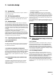
2. Luminaire design In this chapter, recommendations and data are given to enable an optimal luminaire design. 2.2 IEC Recommendations The general recommendations for luminaire design by IEC are also applicable to ‘TL’5 luminaires. Lamp-related data can be found in IEC 61195. 2.3 Miniaturization The ‘TL’5 lamp with a diameter of about 16 mm is 40% thinner than the existing ‘TL’D lamp which has a diameter of 26 mm.The new lamp fits better in existing ceiling system modules as it is 50 mm shorter.
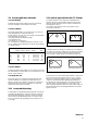
2.5.3 ‘TL’5 lamps and cold conditions If the ambient temperature within the luminaire is lower than the optimum temperature of 35 °C for ‘TL’5 lamps, due to “cold” applications (outdoor, cooling rooms, etc.) One solution is to cover the cold spot with an insulating cap to reach optimum light output. 2.5.4 Vertical burning position As mentioned before the optimum light output with ‘TL’5 lamps is reached at 35 °C in draught-free air with the lamp in horizontal position.
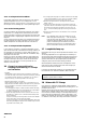
2.9 Various application elements 2.11 Optical opportunities with ‘TL’5 lamps 2.9.1 CE Marking The smaller diameter of ‘TL’5 lamps allows substantially down scaling of the optics to obtain smaller luminaires with the same efficiency and light distribution as the original ‘TL’D luminaire as indicated below in Fig. 2.2. This is ideal in cases where the size of the luminaire is more critical than the efficiency.
Effects of lamp diameter on beam width and luminaire efficiency Beam width ‘TL’D ‘TL’5 ° ° Reflector 1 2 x 19 (narrow beam) Reflector 2 2 x 27 (medium beam) Max. intensity Efficiency ‘TL’D ‘TL’5 ‘TL’D ‘TL’5 cd cd % % 2 x 12.5 1920 2433 78 82 2 x 20.
3. ‘TL’5 lamp specifications 3.1 Range 3.3 Electrical characteristics of ‘TL’5 electrodes The ‘TL’5 range consists of: – – – – ‘TL’5 ‘TL’5 ‘TL’5 ‘TL’5 HE HE HE HE 14W 21W 28W 35W (2 (3 (4 (5 ft) ft) ft) ft) – – – – – ‘TL’5 ‘TL’5 ‘TL’5 ‘TL’5 ‘TL’5 HO HO HO HO HO 24W 39W 54W 49W 80W (2 (3 (4 (5 (5 Electrodes of ‘TL’5 lamps have been designed to fulfil IEC specifications.The minimum and maximum values for resistances with related test currents are given below.
3.4.1 Electrical and lighting characteristics of ‘TL’5 HE lamps In the following tables the electrical and photometrical data are given: Reference ballast Lamp type Colour Nominal conditions at Tamb.
In the following table the dependency on the discharge current is given at top of the lumen curve. Luminous flux and efficacy in the table below are only applicable for colours /827, /830, /835 and /840. For colours /850 and /865 the ratio is in line with the preceding table.
3.4.2 Electrical and lighting characteristics of ‘TL’5 HO lamps In the following tables the electrical and photometrical data are given: Reference ballast Lamp type Colour Nominal conditions at Tamb.
In the following table the dependency on the discharge current is given at top of the lumen curve. Luminous flux and efficacy in the table below are only applicable for colours /827, /830 and /840. For other colours these values are in line with the preceding table.
General colour rendering index (Ra): ≥80 Correlated colour temperatures: 2700 K (/827, incandescent) 4000 K (/840, cool white) 3000 K (/830, warm white) 5000 K (/850, daylight) 3500 K (/835, white 3500) 6500 K (/865, cool daylight) Chromaticity coordinates: x y /827 /830 /835 /840 /850 /865 0,469 0,419 0,438 0,403 0,409 0,397 0,381 0,379 0,343 0,353 0,316 0,336 µW per 5 nm per lumen 3.
2000-11-07 15
4. Operation of ‘TL’5 lamps: Recommendations for ballast design 4.1 Starting characteristics Current controlled preheating 4.1.1 Starting conditions Depending on the available time for preheating, the ballasts should give a preheating current within the following limits: Like all fluorescent lamps, ‘TL’5 lamps have electrodes with some emissive material facilitating ignition, provided it is heated to a sufficiently high temperature.
Energy controlled preheating 4.1.3 Lamp ignition Depending on the available time for preheating, the ballasts should give a preheating energy within the following limits: E=Q+Pxt Lamp type Preheating Preheating time energy J 0,5 s 1,0 s 1,5 s 2,0 s 3,0 s ‘TL’5 HE min. max. 1,35 1,75 2,15 2,70 3,50 4,30 min. max. min. max. min. max. min. max. min. max.
Cold ignition requires a higher ignition voltage.The minimum required ignition voltage can be found in the table below. It is advisable that the lamp current directly after ignition is at least equal to the nominal lamp current.This reduces the time that the lamp is burning with a cold cathode thus the damage to the coil. 4.
4.2.2 Conditions for proper operation of the electrodes For ‘TL’5 HE range: Electrodes in ‘TL’5 lamps consist of a coiled construction of tungsten wire which is filled with emissive material.The lifetime of a fluorescent lamp is determined by the lifetime of the electrode. In order to ensure sufficient electrode lifetime, its temperature should be kept within certain limits.
For ‘TL’5 HO 54W: For ‘TL’5 HO 80W: to be published to be published Figure 4.2.5: “target setting” curve ‘TL’5 HO 54W Figure 4.2.7: “target setting” curve ‘TL’5 HO 80W Note: Also the requirement ILL max.=490 mA should be met. Note: Also the requirement ILL max.=240 mA should be met.
5) The data given for the additional heating by means of the LeadHigh current is directly related to the lamp current. Ballasts which do not make use of this direct relation, should be tested in all practical lamp operating conditions. 6) Information is only given for dimming to 10% of the rated value of the lamp current. It is observed that, at lower dimming levels, the temperature profile of the electrode is different from the one at higher lamp currents.
4.5 Lifetime performance Survivals in % If the ‘TL’5 lamps are operated on electronic gear, designed according to the specifications mentioned in this documentation, at a 3-hour switching cycle (165 minutes on, 15 minutes off), the lamps will have a rated average lifetime of 20,000 burning hours. Operating cycle time min 100 90 690 165 90 45 80 70 Typical values: 5000 hrs: 99% 60 10000 hrs: 98% 50 5000 0 10000 15000 20000 Operating hours Lumen in % Figure 4.4.
6. Definitions Lighting definitions Colour rendering Effect of an illuminant on the colour appearance of objects by conscious or subconscious comparison with their colour appearance under a reference illuminant. Colour rendering index (R) Measure of the degree to which the psychophysical colour of an object illuminated by the test illuminant conforms to that of the same object illuminated by the reference illuminant, suitable allowance having been made for the state of chromatic adaptation.
Annex 1: International Lamp Coding System The lamp industry strives continuously to meet customers’ needs. Its innovative power has led to a tremendous variety of different light sources.To enable customers and experts to find their way within the diversity of products, a general system for the coding of lamps has been developed (see IEC Publication 61231).