User Manual 0150-0241 Phillips ProBridge
© 2004 GE Security All Rights Reserved. Any GE Security software supplied with GE Security products is proprietary and furnished under license and can be used or copied only in accordance with the terms of such license. This document contains proprietary information that is protected by copyright. No part of this document may be reproduced or transmitted in any form or by any means without the prior written permission of GE Security.
Table of Contents 1 Philips ProBridge ........................................................... 4 1.1 1.2 1.3 1.4 1.5 1.6 Philips ProBridge Description .................................................................. 4 Compatibility ............................................................................................. 4 Installation Environment........................................................................... 4 Power......................................................................
1 Philips ProBridge 1.1 Philips ProBridge Description The Kalatel CBR-PB2-PHILIPS is a specific ProBridge unit for interfacing the DVMRe family of digital video multiplex/recorders and providing local keyboard control via a CBR-KB3 or KTD-405 keypad to a Philips AutoDome. Kalatel Components: (1) CBR-PB2-PHILIPS ProBridge. This product includes: • • (1) CBR-PB2-PHILIPS ProBridge unit. (2) P/N 4310-0034: RJ45 to RJ45 cable. Connects the ProBridge and a CBR-KB3 or KTD-405 to the RS-485 Network.
Temperature: Observe the unit’s ambient temperature specifications when choosing a location for the unit. Extremes of heat or cold beyond the specified operating temperature limits may cause the unit to fail. Do not install this unit on top of other hot equipment. Moisture: Do not expose the unit to rain or moisture. Moisture can damage internal components. Do not install this unit near sources of water. RS485 Limitations: Total length of the RS-485 network is limited to 3000’. 1.
1.5 Installation Steps Summary Carefully and completely read the manuals for each piece of equipment before attempting to install and connect this equipment. Before you start connecting other optional accessory equipment to your system, make sure that all, power, video, VCR, and monitor connections are completed, and everything is working correctly. Wire the telemetry equipment according to that unit’s installation instruction.
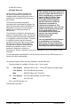
1.6 Connection Diagrams This drawing depicts one Philips AutoDome connected via an RS485/422 network to a Kalatel DVMReTriplex unit, that provides remote PTZ control over Ethernet via WaveReader software, and a CBR-KB3 or KTD-405 keypad.
2 Cable Specifications ProBridge to Kalatel Unit Cable (RS-485) Part Number : 4310-0034B Communication Type: RS-485 Connector Type: RJ45 ,RJ45 Cable Required: 5 Foot RJ45 to RJ45 Triplex RS485 Cable (Supplied). Connects ProBridge to Triplex and CBR-KB3 or KTD-405 keypad.
3 Troubleshooting If you are unable to verify control of the PTZ camera, please do the following: 1. Check that each device is properly powered. 2. Check that all cables and cable connections are correct. 3. Verify that the Dome addresses and Unit ID are correct. 4. If the interface still does not work correctly contact Technical Support.
4 Unit Settings 4.1 Configuring ProBridge Jumpers The unit ships from the factory with the correct settings for most applications and should not require the installer to open the unit and change the jumper settings. However, for trouble shooting purposes we have included the default jumper settings. Opening The ProBridge Place the ProBridge unit face down. Using a small Phillips screwdriver, carefully remove the screws located near each corner of the unit.
Default Jumper Settings The default jumper settings are listed below: PIN # DEFAULT STATUS JP2 RS485 Position JP3 RS485 Position JP4 RS485 Position JP5 RS232 Position P6 Pin 1 Not Installed P6 Pin 2 Not Installed P6 Pin 3 Installed P6 Pin 4 Not Installed P6 Pin 5 Not Installed P6 Pin 6 Not Installed P6 Pin 7 Not Installed P6 Pin 8 Not Installed P6 Pin 9 Not Installed P6 Pin 10 Not Installed P6 Pin 11 Not Installed P6 Pin 12 Not Installed Philips ProBridge 11 0150-0241B
5 Specifications Physical Housing Plastic enclosure. Dimensions (W x L x H) 1.5 x 4.4 x 3.3 in. (38 x 112 x 84 mm) Nominal Weight 4.8 oz (136 g) Shipping Weight 1 lb (453 g) packaged, including the external AC power supply and manual. Color Light gray. Environmental Temperature 0 to 40 °C, operating. Relative Humidity 90%, non-condensing. Electrical AC Power External AC power supply included. Voltage Range: 110 to 240 VAC + 10% Current: 200 mA DC Power DC jack, positive center.
6 Appendix 6.1 RS-485 Addressing and Connections NOTE The Philips ProBridge (CBR-PB2-PHILIPS) is not an addressable device and requires no user settings. The device simply acts as an interpreter, translating the remote telemetry commands into a format useable by the P/T/Z controller. Each camera input, whether a fixed camera or a Pan/Tilt/Zoom (P/T/Z) unit, is connected to a Kalatel unit input. The Kalatel unit has an RS-485 network address, and so does the P/T/Z camera receiver.
6.2 Philip AutoDome Addressing The Philips AutoDome can be addressed from 1 to 9998. The CBR-PB2PHILIPS ProBridge can control camera addresses from 1 to 9998, however the CBR-KB3 keyboard can control cameras from 1 to 1024. WaveReader software can only control cameras from 1 to 8160.
RS485 Network Address Camera Address 025 1 – 32 0769 – 0800 026 1 – 32 0801 – 0832 027 1 – 32 0833 – 0864 028 1 – 32 0865 – 0896 029 1 – 32 0897 – 0928 030 1 – 32 0929 – 0960 031 1 – 32 0961 – 0992 032 1 – 32 0993 – 1024 -- -- -- 255 1 – 32 8129 – 8160 NOTE AutoDome Address Philips AutoDome Addresses are calculated as follows: Philips AutoDome Address = Camera Address + 32 X (Network Address – 1) Philips Data Converter Unit Switch Setting Set the switches on the LTC8780 as
ALT Key Shift Key Aux Keys # ALT 1 1 7 2 1 8 3 1 9 4 2 0 5 2 1 6 2 2 7 2 3 8 2 4 9 2 5 10 2 6 11 2 7 12 2 8 13 2 9 14 3 0 15 3 1 16 3 2 AUX 1 B C D AUX 2 AUX 3 AUX 4 E {F } Preset Key Keyboard Layout 6.
Preset Setup for CBR-KB Keyboard To set a new Preset position: 1. Move the camera to the desired position by using the joystick or arrow keys. 2. Press Preset key twice. The LCD will display: “Set Preshot Number?” Select camera key number 1 to 16 (17 to 32 with Shift key turned on) to set the preset number from 1 to 32. 3. Verify by calling up that preset number: Move to another position then press Preset key once.
7 Warranty Information 7.1 Factory Service If the unit requires factory service, contact the dealer who supplied the unit to you for the correct procedures on returning the unit to the factory or the nearest factory service center. If the dealer is not available, contact the manufacturer of the unit as detailed below and request a Return Material Authorization number (RMA). The unit’s serial number must be provided before an RMA number can be issued.
Note: Customers requesting an estimate prior to repair will be notified by phone. If they cannot be reached, they will be notified by fax. If we are unable to reach the contact person for repair authorization after one phone attempt and two fax attempts, the equipment will be returned without being repaired. We will hold equipment no longer than two weeks.