
Service manual


1-8-58
1-8-59
T6450SCP1
H.V./Power Supply 1/2 Schematic Diagram
NOTE :
The voltage for parts in hot circuit is measured
using hot GND as a common terminal.
CAUTION !
Fixed voltage ( or Auto voltage selectable ) power supply circuit is used in this unit.
If Main Fuse (F601) is blown, check to see that all components in the power supply
circuit are not defective before you connect the AC plug to the AC power supply.
Otherwise it may cause some components in the power supply circuit to fail.
CAUTION
FOR CONTINUED PROTECTION AGAINST FIRE HAZARD,
REPLACE ONLY WITH THE SAME TYPE FUSE.
Voltage indications for PLAY and REC modes on
the Schematic Diagrams are as shown below:
1 2 3
5.0
(2.5)
~
5.0
THE SAME VOLTAGE FOR
BOTH PLAY & REC MODES.
INDICATES THAT THE VOLTAGE
IS NOT CONSISTENT HERE.
PLAY MODE
REC MODE
VOLTAGE CHART (Power off mode)
Ref. No.
IC601
Ref. No.
Q602
Ref. No.
Q603
Q604
Q605
Q606
Q607
Q608
13.1 12.1 0.2 1.6
1234
1.2
0
5.5
0.1 0.7
12.0
10.3
9.7
9.6
6.5
7.36.7
10.3
5.9
1.2
ECB
00.21.8
SDG
1.80304.0
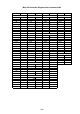
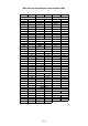
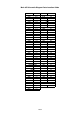
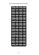
Comparison Chart of
Models and Marks
MODEL MARK
14PV135/07 E
14PV235/07 F
14PV385/07 G
14PV135/01 H
14PV235/01 I
14PV385/01 J
14PV135/58 K
14PV235/58 L
14PV385/39 M