49BDL4150D 55BDL4150D V1.01 www.philips.
Safety Instructions Safety precautions and maintenance WARNING: Use of controls, adjustments or procedures other than those specified in this documentation may result in exposure to shock, electrical hazards and/or mechanical hazards. Read and follow these instructions when connecting and using your display: Operation: • Keep the display out of direct sunlight and away from stoves or any other heat sources.
Stability Hazard. The device may fall, causing serious personal injury or death. To prevent injury, this device must be securely attached to the floor/wall in accordance with the installation instructions. Read and follow these instructions when connecting and using your display: • Unplug the display if you are not going to use it for an extensive period of time. • Unplug the display if you need to clean it with a slightly damp cloth. The screen many be wiped with a dry cloth when the power is off.
Envision Peripherals Inc. 490 N McCarthy Blvd, Suite #120 Milpitas, CA 95035 USA Europe – EU Declaration of Conformity This device complies with the essential requirements of the Radio Equipment Directive (2014/53/EU).
Canada: Industry Canada statement: This device complies with RSS-247 of the Industry Canada Rules. Operation is subject to the following two conditions: (1) This device may not cause harmful interference, and (2) this device must accept any interference received, including interference that may cause undesired operation. Ce dispositif est conforme à la norme CNR-247 d’Industrie Canada applicable aux appareils radio exempts de licence.
Electric, Magnetic and Electromagnetic Fields (“EMF”) 1. We manufacture and sell many products targeted at consumers, which, like any electronic apparatus, in general have the ability to emit and receive electromagnetic signals. 2. One of our leading Business Principles is to take all necessary health and safety measures for our products, to comply with all applicable legal requirements and to stay well within the EMF standards applicable at the time of producing the products. 3.
Paikka/Ilmankierto VAROITUS: SIJOITA LAITE SITEN, ETTÄ VERKKOJOHTO VOIDAAN TARVITTAESSA HELPOSTI IRROTTAA PISTORASIASTA. Plassering/Ventilasjon ADVARSEL: NÅR DETTE UTSTYRET PLASSERES, MÅ DU PASSE PÅ AT KONTAKTENE FOR STØMTILFØRSEL ER LETTE Å NÅ.
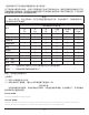
《废弃电器电子产品回收处理管理条例》提示性说明 为了更好地关爱及保护地球,当用户不再需要此产品或产品寿命终止时,请遵守国家废弃电器电子产品 回收处理相关法律法规,将其交给当地具有国家认可的回收处理资质的厂商进行回收处理,不当利用或 者处置可能会对环境和人类健康造成影响。 警告 此为 A 级产品。在生活环境中,该产品可能会造成无线电干扰。在这种情况下,可能需要用户对 干扰采取切实可行的措施。 限用物質及其化學符號 單元 鉛 (Pb) 汞 (Hg) 鎘 (Cd) 六價鉻 (Cr+6) 多溴聯苯 (PBB) 多溴二苯醚 (PBDE) 塑料外框 ○ ○ ○ ○ ○ ○ 後殼 ○ ○ ○ ○ ○ ○ 液晶面板 - ○ ○ ○ ○ ○ 電路板組件 - ○ ○ ○ ○ ○ 底座 ○ ○ ○ ○ ○ ○ 電源線 - ○ ○ ○ ○ ○ 其他線材 - ○ ○ ○ ○ ○ 遙控器 - ○ ○ ○ ○ ○ 喇叭(選配) - ○ ○ ○ ○ ○ 風扇(選配) - ○ ○ ○ ○ ○
End-of-Life Disposal Your new Public Information Display contains materials that can be recycled and reused. Specialized companies can recycle your product to increase the amount of reusable materials and to minimize the amount to be disposed of. Please find out about the local regulations on how to dispose of your old display from your local Philips dealer. (For customers in Canada and U.S.A.) This product may contain lead and/or mercury. Dispose of in accordance to local-state and federal regulations.
Batteries For EU: The crossed-out wheeled bin implies that used batteries should not be put to the general household waste! There is a separate collection system for used batteries, to allow proper treatment and recycling in accordance with legislation. Please contact your local authority for details on the collection and recycling schemes. For Switzerland: The used battery is to be returned to the selling point.
Table Of Contents 1. 5.12. Supplementary............................................................................44 Unpacking and Installation........................................................1 1.1. Transportation and Unpacking.............................................1 1.2. Package Contents.........................................................................3 1.3. Installation Notes..........................................................................3 1.4. Mounting on a Wall.........
1. Unpacking and Installation 1.1. Transportation and Unpacking Notice for transportation • Always keep the carton in a vertical position. Do NOT place the carton in any other direction. • Do NOT place any object on the carton. • Do NOT apply shock/vibration to the product. • Move the carton by stacker. • Do NOT drop the product. Strong impacts may damage the components inside.
• Move the display from the carton by two adults with both hands. • Do not touch the screen of display to avoid possible scratches. Move the display by holding the handles. • Keep the display vertically when moving it. 90° • Place the display vertically and its weight should spread evenly on the surface.
Before installing the display • This product is packed in a carton, together with the standard accessories. • Any other optional accessories will be packed separately. • Move the display by at least two (2) adults. • After opening the carton, ensure that the contents are complete and in good condition. 1.2.
1.4. Mounting on a Wall To mount this display on a wall, a standard wall-mounting kit (commercially available) is required. It is recommended that you use a mounting interface that complied with TUV-GS and /or UL1678 standard in North America. 49BDL4150D 55BDL4150D Protective Sheet Protective Sheet VESA Grid VESA Grid Table Table 1.
Caution: To prevent the display from falling: • For wall or ceiling mounting, we recommend that you install the display with metal brackets which are commercially available. For detailed instructions about the installation, refer to the guide provided with the bracket. • To prevent the display from falling in case of earthquake or other natural disaster, please consult the manufacturer of the bracket for the mounting location.
1.5. Mounting in Portrait Orientation This display can be installed in portrait position. 1. If the table stand is attached, remove it first. 2. Rotate the display counter-clockwise by 90°. The “ ” logo should be on the RIGHT side when facing the display. 90 90 1.5.1. How to remove the logo 1. Prepare a piece of paper with a cutting area of logo as a protector to prevent the front bezel from scratching. 1 2 3 2. Use a knife and carefully remove the logo sticker with the paper placing beneath. 3.
1.6. Installing the optional table stand 1. You can order the optional table stand for this display by the Model Number: BM05922. 2. Installing process: (1) Ensure the display is powered off. (2) Spread a protective sheet on a flat surface. (3) Hold the handles and place the display face-down on the protective sheet. (4) Assemble the tube to the display as shown below. (5) Insert the stand to the tube and fix the stand by using the thumb screw.
2. Parts and Functions 2.1. Control Panel 9 1 2 3 4 5 6 7 8 9 1 Use this button to turn the display on or put the display to standby mode. Remote control sensor and power status indicator • Receives command signals from the remote control. • Indicates the operating status of the display without OPS: - Lights green when the display is turned on 2 Switch the audio mute ON/OFF. - Lights red when the display is in standby mode Choose the input source.
2.2. Input/Output Terminals 49BDL4150D RS232 LAN MICRO SD OTG USB 2.0 USB 3.0 9 7 10 8 6 5 DP OUT 4 USB Service Port 26 EXT. SPK TERMINAL SPEAKER SWITCH AUDIO OUT AUDIO IN SPDIF OUT IR-OUT IR-IN VGA IN 100-240V 50-60Hz 2.5A HDMI1 IN 2 1 1 3 HDMI2 IN HDMI3 IN RS232 IN RS232 OUT 14 AC IN 16 MAIN POWER SWITCH 17 USB SERVICE PORT 19 NOTE: It’s for updating firmware only. 20 AC power supply to the AC IN jack of a media player.
55BDL4150D 26 EXT. SPK TERMINAL 25 SPEAKER SWITCH AUDIO OUT 23 AUDIO IN SPDIF OUT 21 IR-OUT IR-IN 24 22 20 19 VGA IN 18 17 DP OUT DP IN 100-240V 50-60Hz 2.5A 1 2 3 USB 2.0 USB Service Port 4 1 DP OUT OTG 5 6 RS232 MICRO SD USB 3.0 7 8 9 AC OUT 14 AC IN 16 MAIN POWER SWITCH 17 USB SERVICE PORT 19 NOTE: It’s for updating firmware only. 20 AC power supply to the AC IN jack of a media player.
2.2.1. Inserting the batteries in the remote control The remote control is powered by two 1.5V AAA batteries. To install or replace the batteries: 1. Press and then slide the cover to open it. 2. Insert the batteries with the correct polarity (+) and (–). 3. Replace the cover. Caution: Incorrect use of batteries may cause leakage or explosion. Be sure to follow the instructions below: • Insert “AAA” batteries with the correct polarity (+ and -). • Do not mix battery types.
2.3. Remote Control 5 [ ] LIST button Reserved. 2.3.1. General functions 6 NAVIGATION buttons [ ] 1 Root Menu: Go to the OSD of Smart picture. Main Menu: Move the selected item up to make adjustment. IR Daisy Chain Menu: Increase the controlled Group ID number. 2 [ ] Root Menu: Go to the OSD of Audio source. 3 12 4 13 5 Main Menu: Move the selected item bar down to make adjustment. IR Daisy Chain Menu: Decrease the controlled Group ID number.
2.3.2. ID Remote Control Press the [ID] button and the red LED blinks twice. 1. Press [ID SET] button for more than 1 second to enter the ID Mode. The red LED lights up. Press the [ID SET] button again will exit the ID Mode. The red LED lights off. Set remote control ID number when using several displays. Press the digit numbers [0] ~ [9] to select the display to be controlled. For example: press [0] and [1] for display No.1, press [1] and [1] for display No.11. The numbers available are [01] ~ [255]. 2.
2.3.3. Remote Control buttons on Android source 3 [ ] SOURCE button Select an input source. 4 [ ] HOME button Access the OSD menu. 1 5 [ ] LIST button 1. In the content of the web page, move the focus up to the next clickable items. 2. Move the focus up to the next control or widget such as buttons. 2 / / 6 3 12 4 13 5 14 1. Navigate through menus and choose items. 2. In the content of the web page, these buttons are to control the scroll bar of the screen. Press up or down.
14 [ ] INFO button 1. Display information about the current input signal. 2. Media Player -> Compose -> edit or new add playlist -> choose any media files -> press to show the information of the chosen media file. 15 [ ] OPTIONS button Open the toolbox from Media Player or PDF Player. 1. Media Player ->Compose -> Edit or new add playlist -> press to open a toolbox. Toolbox will be slide from the left side of the screen. 2. PDF Player ->Compose -> Edit or new add playlist -> press to open a toolbox.
2.4. • SD card Cover Use the SD card cover and screws to cover the Micro SD card. 2.5. 4G Module 1. Remove the service cover. 2. Locate Wi-Fi/4G module. 3. Install the 4G module. 4. Install the Antenna cable.
3. Connecting External Equipment 3.1. Connecting External Equipment (DVD/VCR/VCD) 3.1.1. Using HDMI video input DVD / VCR / VCD HDMI Out HDMI1 IN HDMI2 IN HDMI3 IN [HDMI IN] 3.2. Connecting a PC 3.2.1. Using VGA input [VGA AUDIO IN] AUDIO OUT Audio Out PC AUDIO IN SPDIF OUT IR-OUT VGA Out D-Sub 15 pin IR-IN VGA IN [VGA IN] 3.2.2.
3.2.3. Using HDMI input PC HDMI1 IN HDMI2 IN HDMI3 IN HDMI Out [HDMI IN] 3.2.4. Using DisplayPort input PC DisplayPort Out [DisplayPort IN] DP IN 3.3. Connecting Audio Equipment 3.3.1. Connecting external speakers EXT.
3.3.2. Connecting an external audio device Audio In [AUDIO OUT] SPEAKER SWITCH AUDIO OUT Stereo Amplifier AUDIO IN SPDIF OUT [SPDIF OUT] 3.4. Connecting Multiple Displays in a Daisy-chain Configuration You can interconnect multiple displays to create a daisy-chain configuration for applications such as a menu board. 3.4.1. Display control connection Connect the [RS232 OUT] connector of DISPLAY 1 to the [RS232 IN] connector of DISPLAY 2.
3.4.2. Digital video connection Connect the [DP OUT] connector of DISPLAY 1 to the [DP IN] connector of DISPLAY 2. DISPLAY 1 DISPLAY 2 PC [DP] [DP IN] 3.5. [DP OUT] [DP IN] IR connection External IR Receiver DISPLAY 1 [IR IN] DISPLAY 2 [IR IN] [IR OUT] DISPLAY 1 DISPLAY 2 [RS-232C OUT] [RS-232C IN] NOTE: 1. The remote control sensor of this display will stop working if the [IR IN] is connected. 2. IR loop through connection can support up to 9 displays. 3.
3.6.
4. Operation • NOTE: The control button described in this section is mainly on the remote control unless specified otherwise. 4.1. Settings: go to Settings page. Applications: show all apps. ] SOURCE button. 2. Press [ ] or [ ] button to select a device, then press [ 4.2. Home page of Admin mode, this page consists of the following itmes: “Settings”, “Apps”, “Network” “Storage” and “Help”. Watch the Connected Video Source 1.
3) Network page 4) Storage page 5) Help page Display QR to link to Philips support website.
4.4. Media Player 4.4.2. Media Player introduction: 1. The main page of Media Player, this page consists of three options: “Play”, “Compose” and “Settings”. Play: select a playlist to play. Compose: edit a playlist. Settings: setting the properties of Media Player. 4.4.1. OSD menu interaction with media player: 1. Boot on source: - Input: ■ If you select Media player as the source, the system will enter media player automatically after the boot process is completed.
7. If “Sort” is selected, you can customize the file order severally. 5. To edit or delete a non-empty playlist, select the desired playlist that has a pencil icon on right side of the file. 8. After selecting the desired file, press “Info” key to obtain the detailed information. 6. Once you start to edit a playlist, a menu is displayed as below. Source - files saved in the memory storage. Playlist – files saved in the playlist.
Step 4. Start media player App, it will import the text file of media player automatically. 11. Select “Settings” on the main page, there are 3 options available: “Repeat Mode”, “Slideshow Effect” and “Effect Duration”. Repeat Mode: set the repeat mode. Slideshow Effect: photo slideshow effect. Effect Duration: duration of photo effect. Note. Once the playlist file (text) is imported, any changes made through the remote control will not be recorded in the playlist text file. 12.
4.5. Browser 4. Press Option then left side will pop up a list. Import: Import the file of URL list Export: Export the file of URL list Delete all: Delete all URL records from the main screen Back: Close the side menu bar Before using this feature, ensure that the system is connected successfully to the network. (See 5.1. Wi-Fi & 5.2. Ethernet) 1. Main page of “Browser” App which allows you to make related settings. 4.1 Import 2. Press “Compose” then enter next page. Users can choose 1~7.
• Import the browser file and the URL will be listed on the screen. • The file format supported for import is “.txt”. • A dialog box displays the path of the file to be saved as well as the file name. Press the “Save” button to save the URL. 5. Press the “OK” button to save the URL record. 4.2 Export: • • Select export 6. If you select a non-empty item from the URL list, a message will appear asking if you want to edit or play the URL. If you select “Edit” a dialog box allows you to edit the URL.
7.2 Reload Let user set webpage reload time. a. If the enable check box is unchecked, the default reload time is 60 seconds. Note: On this case, the webpage reload only on network state changes. If network state always connect, the webpage doesn’t reload after 60 seconds. 7. Press “Settings” then enter next page. b. If the enable check box is checked, you can set the reload time. 8. OSD menu interaction with Browser 8.
9. How to edit url list via FTP Step 1. Create a text file of media player. - File name: bookmarklist.txt. - Content: Step 2. Copy bookmarklist.txt to “philips” folder of your internal storage. You may use FTP to do this. - File path: /storage/emulated/legacy/philips (for DL, PL) Ex. /storage/emulated/legacy/philips/bookmarklist.txt Step 3. Start Browser App, it will import the text file of Browser automatically. Note.
4.6. PDF Player 2. Select “Play” on the main page, first you should select one playlist to play between FILE 1 and FILE 7. The pencil icon means that the playlist contains the content. 4.6.1. OSD menu interaction with PDF player: 1. Boot on source: - Input: ■ If you select “PDF player” as the source, the system will launch PDF player automatically after the boot process is completed. - Playlist: ■ 0: go to the main page of PDF player.
5. To edit or delete a non-empty playlist, select the desired playlist that has a pencil icon on right side of the file. 8. Select “Settings” on the main page, there are two options available: “Repeat Mode” and “Effect Duration”. Repeat Mode: set the repeat mode. Effect Duration: duration of photo effect. 6. Once you start to edit a playlist, a menu is displayed as below. Source- files saved in the memory storage. 9. How to edit the PDF list via FTP? Step 1. Create a text file of PDF player.
4.8. Color Hotkey: Custom App Blue: Zoom in (+10%) Set up the application for Customer Source. Yellow: Zoom out (-10%) Note: (1) Only display the App installed by user. OK: Restore zoom Arrow keys: (2) System’s pre-installed App is not displayed. Up/Down/Left/Right: Adjust the page. (when the page is zoomed in/ out) 4.8.1. OSD Menu operation: RCU: Source > Custom Left: Previous page. (when the page is not zoomed in/out) Right: Next page.
5. Setting (2) Mac Address Note: Main items: Ethernet will be disabled automatically if Wi-Fi is connected to the network correctly. (1) Wi-Fi (2) Ethernet (3) More (available when 4G module is connected) 5.3. (4) Signage Display (5) Display More (available when 4G module is connected) Control Cellular networks. (6) Apps Note : (7) Security 1. Available only when 4G module is connected. (8) Input method 2.
Scenario introduction: Case 1 When the system cannot find bootanimation.zip file under SD and USB, the file list will be empty. The “Save” and “Forget” options become gray. 2. Boot Logo 1) Scalar OSD menu to control Android boot logo Scalar OSD menu operation RCU: Home > Configuration2 > Logo > On/Off/User Under user mode, select your own animation file of boot logo file. Case 2 Note: 2) When boot logo is selected, the system will check if bootanimation.zip is present in the USB and SD card.
3) If the logo item of OSD menu is On or Off, then the boot animation in Android settings is not selectable. Set the interval time for deleting the screenshot images. The available options are “One day” and “One week”. 7) Send screenshots via email Send the screenshot images as an e-mail attachment to the administrator. Please refer to Email notification. Note: Ensure that Email setting is done, so that the screenshot can be sent immediately. 3. Screenshot 4.
5.4.2. Server Settings Gmail safety setting If a problem occurs when sending the e-mail via Gmail, please visit Google website: 1. E-mail Notification Enable/disable the E-mail notification feature. Set E-mail notification configuration after enabling this feature. https://www.google.com/settings/security/lesssecureapps for checking the security setting of your Google Account. Then turn on “Access for less secure apps”.
2. FTP Click the checkbox to enable/disable the FTP server feature. After enabling this feature, files can be shared on the FTP. 3) Storage Path Show default path: Internal storage. Note: 1) Account Display the path of internal storage which is unchangeable. Set FTP account 4) Port Note: Set FTP port number. Input limitation Note: (1) Length: 4-20 characters Input limitation: (2) Format: I. English letter: a-z and A-Z II.
5.4.4. Network application (2) If the device is equipped with network function, but is not connected to the remote control server, a message “Server is disconnected” will appear. 1. Proxy Enter the Host and Port of the proxy server. (3) Show “Server is unbinded” if the remote control server replies its unbound status. (4) Show “Server is binded” if the device is bound with Sever successfully. (5) Show Error PIN code if the PIN code is not correct. 4.
5.4.5.1 Clear Storage 5.4.5.3 Import & Export The purpose is to clear data in the folder “Philips”. It is divided into 4 modes: This function allows you to import/export the settings and 3rd party APK from/to other device. (1) Clear all Philips folders. Notes. (2) Clear the folder “Philips” from the internal storage only. (1) Saved file name: A. Settings_global.xml B. Settings_secure.xml C. Settings_system.xml D. Signage_settings.db E. AndroidPDMediaPlayerData.db F. AndroidPDPdfData.db G.
5.4.5.5 External Storage A confirmation dialog box is displayed before importing the settings and apps. Enable: lock the SD card/USB External Storage. Disable: unlock the SD card/USB External Storage. Note: Insert the SD card/USB External Storage back to the device after unlocking the external storage. 5.4.5.4 Clone Media File This function allows you to copy the media files from the folder “Philips” of your source storage (internal, SD card or USB). 1.
5.4.7. System update 5.5. 1. Local update Display Set the font size of display from Small/Default/Large/Largest. The system will auto search “update.zip” from the internal storage, USB disk or SD card. If it is found, it will be shown on the list. Note: a. It only supports Android full image. b. The file name should be “update.zip” c. The file should be stored in the root folder of your storage. 5.6. Apps Display application information. (2) After selecting the file “update.
5.8. Input method 5.10. Developer options (1) On-screen keyboard enable: Show or hide the software keyboard on screen. Android developer options. For more information please visit https://developer.android.com/index.html (2) Email auto-complete: Autocomplete for email addresses in android. 5.11. About 5.9. View the following information of the system: Date & time (1) Legal Information: show the open source licenses. (2) Android version Allow users to change time zone settings.
5.12. Supplementary 5.12.1. Quick Info - p 1 0 part0 - p 0 0 part1 a. The first line Press “Info + 77” to startup quick info. 1920 and 1080 define the width and height of the screen resolution. Quick info will show “Network” and “Monitor Information”. 30 is the frame rate in fps (frames per second) i.e. number of images to display per second. Note: Operation hours: updates every minute. b. The second and third lines have a same format. Heat status : updates every 5 seconds.
If using WinRAR, set “Compression method” to “Store”. (b) Via Adb Shell 1. Make sure that your PC can connect to Philips Android Signage Display using adb. 2. Prepare your apk in a folder(for example, C:\apkfolder) on your PC. 3. Execute the following instruction using command line tool. C:\apkfolder> adb install -r apk_name.apk (c) Via Customized Intent 1. If you develop an apk which can download any Android App, then your APK can issue a customized intent. 2.
6. OSD Menu 6.2. An overview of the On-Screen Display (OSD) structure is shown below. You can use it as a reference for further adjustment of your display. 6.1. OSD Menu Overview 6.2.1. Picture menu Picture Navigating the OSD Menu Screen 6.1.1. Navigating the OSD menu using the remote control SOURCE Audio FORMAT P PIP Configuration 1 LIST Brightness 70 Contrast 50 Sharpness 50 Black level 50 Tint Color Noise reduction Medium Gamma selection 2.
Or, you can adjust the color tones per 100K in the range of 2000K to 10000K. NOTE: This item applies to VGA input only. {Picture} - {Color temperature} - {User} setting to [User 2] Adjust to improve the focus, clarity and stability of the image. Clock phase Smart picture NOTE: This item applies to VGA input only. The following smart picture modes are available for: Zoom mode • PC mode: {Standard} / {Highbright} / {sRGB}. • Video mode: {Standard} / {Highbright} / {Cinema}.
6.2.4. PIP menu V position Moves the vertical position of image up or down. Picture Screen Screen reset Reset all settings in the Screen menu to factory preset values. Audio 6.2.3.
• The PIP function is available only for certain signal source combinations as shown in the table below.
6.2.6. Configuration2 menu Example: Tiling matrix sets to 4 • 1 2 3 4 5 6 7 8 9 10 11 12 13 14 15 16 {Auto ID} The option are: {Start} / {End}. The default setting is {End}.
The options are: {Off} / {On} (default). • Configuration2 reset NOTE: To enable or disable the keyboard control lock, press [ ] and [ ] buttons simultaneously and keep pressing continuously for more than 3 seconds. Reset all settings in Configuration2 menu to the factory preset values. 6.2.7. Advanced option menu Configuration 2 Advanced option Input {Lock All} / {Lock all but Volume} / {Lock all but Power} - Disable the keyboard function.
Frame comp. - Off NOTE: It is recommended that you set up the current date and time in the {Date and time} menu before using this function. 1. Press [OK] or [ ] button to enter the submenu. _ _ _ _ _ • {Enable} - Enable or disable the Tiling function.
Specific commands to control monitors are defined in a separate Monitor Control Command Set (MCCS) standard. APM DDC/CI monitors are sometimes supplied with an external color sensor to allow automatic calibration of the monitor’s color balance. Some tilting DDC/CI monitors support an auto pivot function, where a rotation sensor in the monitor enables the operating system to keep the display upright as the monitor is moved between its portrait and landscape positions.
PIP audio Select the audio source in PIP (Picture-in-Picture) mode. • {Main} - Select audio from the main picture • {Sub 1} - Select audio from the sub1 picture. • {Sub 2} - Select audio from the sub2 picture. • {Sub 3} - Select audio from the sub3 picture. Input reset Reset all settings in the Input menu to factory preset values.
7. Supported Media Formats USB Multimedia Codec Formats Video Decode Type Video Codec Container Decode Encode Channel Remark MPEG program stream (.DAT, .VOB, .MPG, .MPEG) MPEG1/2 MPEG1/2 MPEG transport stream (.ts) Max Resolution: 1080P@60fps V MP4 (.mp4) Max Bit Rats : 40Mbps AVI (.avi) MKV (.mkv) MP4 (.mp4) MPEG-4 MPEG4 AVI (.avi) Max Resolution: 1080P@60fps V Max Bit Rats : 40Mbps MKV (.mkv) H.263 H.263 FLV (.flv) Max Resolution: 1080P@60fps V AVI (.
Image Decode Type Image Codec JPEG JFIF file format 1.
8. Input Mode VGA/DVI timing support: Item Mode Resolution H.Freq. (KHz) V.Freq. (Hz) 1 IBM VGA 10H 640x350 31.469 70.086 2 IBM VGA 12H 640x480 31.469 59.94 3 MACINTOSH 640x480 35 66.67 4 VESA 640x480 37.861 72.809 5 VESA 640x480 37.5 75 6 IBM VGA 3H 720x400 31.469 70.087 7 VESA 800x600 35.156 56.25 8 VESA 800x600 37.879 60.317 9 VESA 800x600 48.077 72.188 10 VESA 800x600 46.875 75.000 11 MACINTOSH 832x624 49.726 74.
4K2K Item Resolution H.Freq. (KHz) V.Freq. (Hz) 1 3840x2160 53.946 23.900 2 3840x2160 54 24.000 3 3840x2160 56.25 25.000 4 3840x2160 67.432 29.900 5 3840x2160 67.5 30.000 6 4096x2160 54 24.000 7 3840x2160 135 60.
9. Pixel Defect Policy We strive to deliver the highest quality products and use some of the industry’s most advanced manufacturing processes whilst practicing stringent quality control. However, pixel or sub-pixel defects on the PDP / TFT panels used in Plasma- & LCD- displays are sometimes unavoidable.
9.4. Dark Dot Defects Black dot defects appear as pixels or sub-pixels that are always dark or “off ”. These are the examples of black dot defects: One dark dot 9.5. Two adjacent dark dots = 1 pair of dark dots Two dark dots, specifications defines the minimum distance between dark dots Proximity of Pixel Defects Because pixel and sub-pixels defects of the same type that are nearby one another may be more noticeable, Philips also specifies tolerances for the proximity of pixel defects.
10. Cleaning and Troubleshooting 10.1. Cleaning Caution When Using the Display • Do not bring your hands, face or objects close to the ventilation holes of the display. The top of the display is usually very hot due to the high temperature of exhaust air being released through the ventilation holes. Burns or personal injuries may occur if any body parts are brought too close.
10.2. Troubleshooting Symptom Possible Cause Remedy No picture is displayed 1. The power cord is disconnected. 1. Plug in the power cord. 2. The main power switch on the back of the display is not switched on. 2. Make sure that the power switch is switched on. 3. The selected input has no connection. 3. Connect a signal connection to the display. 4. The display is in the standby mode.
How to setup the settings in the menu to control all the monitors at the same time and individually via RC? Daisy chained by RS232 and no IR cable 1. The first display sets as “Primary” on OSD (Advanced option/IR control item), others set as “Secondary”. 2. The setup OSD will show on top left side of the display.(Toggle MENU will show again if it disappear) 3. Default setting: ID NO: 0, GP NO: 0, this setting can control all displays by IR.
11. Technical Specifications Display: Specifications Item 49BDL4150D 55BDL4150D Screen Size (Active Area) 1232 mm / 48.5 inches 1387 mm / 54.6 inches Aspect Ratio 16:9 16:9 Number of pixels 3840 (H) x 2160 (V) 3840 (H) x 2160 (V) Pixel pitch 0.27963 (H) x 0.27963 (V) [mm] 0.315 (H) x 0.315 (V) [mm] Displayable colors 1.07 Billion colors 1.
General: Specifications Item 49BDL4150D 55BDL4150D Power Input 100 - 240V~, 50 - 60Hz, 5.0A 100 - 240V~, 50 - 60Hz, 5.5A Power Output 100 - 240V~, 50 - 60Hz, 2.5A 100 - 240V~, 50 - 60Hz, 2.5A Power Consumption (Max) 194 W 211 W Power Consumption (typ.) 135 W 150 W Power Consumption (Standby & Off) <0.5 W <0.5 W Dimensions (Without Stand) [W x H x D1(Wall Mount) 1104.2 x 637.0 x 65.4 mm / 69.6 mm / D2(Handle)] 1240.0 x 713.4 x 65.4 mm / 69.6 mm Weight (Without Stand) 20.
2019 © Koninklijke Philips N.V. All rights reserved. Philips and the Philips Shield Emblem are registered trademarks of Koninklijke Philips N.V. and are used under license from Koninklijke Philips N.V. Specifications are subject to change without notice.