Guide d’installation rapide / Quick installation guide WelcomeEye Comfort DES9500VDP - 531000 WelcomeEye Compact DES9300VDP - 531004 FR. Notice téléchargeable sur philips.com IT- Il manuale è disponibile anche su www.philips.com. ES - Manual que puede descargar en philips.com PT - Manual de instruções disponível no site philips.com GB - Downloadable instructions at phillips.com NL - De handleiding kan gedownload worden op philips.com D - Anleitung kann auf philips.
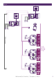
Fig. 1 ZZ Off Of OnOff (Master) Z On Off DES 9900 VDP + - 1/3 2/4 Made in P.R.C CFI Extel ZI de Fétan, 01600 Trévoux FRANCE 120 m max 2 1 1 2 1 2 3 4 5 6 7 8 1 1 2 2 IP44 2 Made in P.R.
Fig. 2 1 2 1 3 4 2 5 6 IP44 7 8 1 1 2 2 1 3 4 2 5 6 IP44 1 2 CFI Extel ZI de Fétan, 01600 Trévoux FRANCE 7 8 1 1 2 2 On Of On + - 2/4 CFI Extel ZI de Fétan, 01600 Trévoux FRANCE On (Master) 1/3 DES 9900 VDP Made in P.R.
Fig.
SOMMAIRE 1 CONSIGNES DE SÉCURITÉ................................................................p.2 2 CONTENU DU KIT.................................................................................p.2 3 GÉNÉRALITÉ..........................................................................................p.3 4 NOMENCLATURE.................................................................................p.3 5 INSTALLATION DU PRODUIT...........................................................p.
1. CONSIGNE DE SÉCURITÉ Important ! • Veuillez lire le manuel d’utilisation soigneusement avant d’installer ou d’utiliser ce produit. • Si vous installez ce produit pour d’autres, pensez à laisser le manuel ou une copie à l’utilisateur final. Avertissement : • Les différents éléments ne devront être démontés que par un technicien autorisé.
3. GÉNÉRALITÉ Ce visiophone est composé d’un poste de réponse intérieur avec écran tactile et d’une platine extérieure avec interphone et caméra permettant de voir et communiquer avec le visiteur qui a sonné. Il est facile d’installation puisque 2 fils sont nécessaires pour toutes les fonctions (sonnerie, vidéo, interphone, commandes gâche et automatisme). La technologie WelcomeEye vous permet de partager la platine de rue entre 2 familles. Chaque famille peut posséder jusqu’à 3 moniteurs.
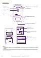
Platine de rue : LED blanche (vision de nuit) Capteur crépusculaire Microphone Objectif de la caméra Haut-parleur Éclairage porte-nom 1 1 2 1 2 3 4 5 6 7 8 Vis antivol de fixation 2 2 1 Switch de programmation Réglage volume hautparleur 1 1 2 1 2 3 4 5 6 7 8 1 2 1 2 1 2 1 2 3 4 5 6 7 8 1 2 2 Bornier de raccordement des fils CFI Extel ZI de Fétan, 01600 Trévoux FRANCE Made in P.R.C IP44 Made in P.R.
5. INSTALLATION DU PRODUIT Conseils et notes importantes : - Afin de profiter pleinement de votre platine de rue, nous vous conseillons de la paramétrer (mode 1 ou 2 familles, 1 ou 2 platines, volume du haut-parleur), avant installation définitive. Pour cela, un branchement sur table peut être nécessaire afin de vérifier que les réglages ont été effectués correctement.
2. Paramétrage de la platine (voir fig. 1, fig. 2 ou fig. 3) a. Paramétrage du numero de la platine : Placer le switch 2 à gauche sur la platine n°1 et à droite sur la platine n°2. b. Paramétrage du nombre de famille : Placer le switch 1 à gauche pour être en mode une famille et à droite pour être en mode 2 familles. c. Réglage du volume de la platine : Tourner le réglage volume à l’aide d’un tournevis cruciforme afin de régler le niveau sonore de la platine. 3.
4 – Mettre des chevilles adaptées au support (celles fournies conviennent pour des murs en matériaux pleins). 5 – Fixer le support mural. 6 – Raccorder les 2 fils de la platine de rue et les 2 fils d’alimentation en respectant bien le schéma de câblage. 7 – Mettre en place le moniteur sur son support mural. 8 - En fonction de la configuration choisie, et lorsque l’ensemble du cablage est terminé, un paramétrage de l’interface peut-être necessaire.
1 - Dévisser la vis antivol sous la platine de rue. 2 - Basculer la façade de la platine de rue vers l’avant. 3 – L’objectif de la platine doit être placé à une hauteur d’environ 1m60 du sol. 4 – Faire des repères. 5 - Percer. 6 - Utiliser des chevilles adaptées à la nature du support (les vis fournies conviennent pour des murs en matériaux pleins). 7 – Raccorder les deux fils provenant du moniteur et si besoin raccorder la gâche éléctrique et le portail (voir section 1. Cablage).
- Vision nocture (Leds blanches) - Commande de gâche 12V/1,1A - Commande de portail : pouvoir de coupure 12V/2A - IP44 - Température d’utilisation : -20°C / +50°C WelcomeEye Outdoor : (Platine de rue supplémentaire) réf : 531006 - Capteur C-MOS couleur 900TVL - Angle de vue H130° / V 90° - Vision nocturne (Leds blanches) - Commande de gâche 12V/1.
WelcomeEye Lock - DES 1100 EDL (réf: 531009) WelcomeEye Power - DES 1000 DPS (réf: 531010)** WelcomeEye TAG - DES 1000 ACI (réf: 531011)** ** Réferez-vous à la notice complète WelcomeEye Connect/Touch disponible sur le site www.philips.com pour plus d’informations. * Réferez-vous à la notice complète WelcomeEye Comfort/Compact disponible sur le site www.philips.com pour plus d’informations. 8. ASSISTANCE TECHNIQUE - GARANTIE La FAQ est disponible dans la notice complète téléchageable sur www.philips.com.
Philips et l’emblème bouclier Philips sont des marques déposées de Koninklijke Philips N.V. et sont utilisées sous licence. Ce produit a été fabriqué par et est vendu sous la responsabilité de CFI Extel SAS, et CFI Extel SAS est le seul garant de ce produit. 9. MESURES DE SÉCURITÉ Les dommages provoqués par le manque de conformité au manuel mènent à l’expiration de la garantie.
TABLE OF CONTENTS 1 SAFETY INSTRUCTIONS...................................................................p.2 2 CONTENTS OF THE KIT....................................................................p.2 3 GENERAL INFORMATION................................................................p.3 4 NOMENCLATURE...............................................................................p.3 5 PRODUCT INSTALLATION...............................................................p.5 1. Wiring.
1. SAFETY INSTRUCTIONS Important! • Please read the user manual carefully before installing or using this product. • If you are installing this product for a third party, please remember to leave the manual or a copy of it with the end user. Warning: • The various components may only be dismantled by an authorised technician. Safety precautions: • To ensure the safe operation of the system, installers, users and technicians must follow all the safety procedures described in this manual.
3. GENERAL This videophone consists of an indoor answering unit with a touch screen and an outdoor panel with an intercom and camera, allowing you to see and communicate with the visitor who has pressed the bell. It is easy to install as only two wires are needed for all functions: bell, video image, intercom and strike plate and automatic opener controls. The WelcomeEye technology allows you to share the intercom panel between 2 families. Each family can own up to 3 monitors.
Intercom panel White LED (night vision) Twilight sensor Microphone Camera lens Loudspeaker Name holder lighting 1 1 2 1 2 3 4 5 6 7 8 Tamper-resistant retaining screw 2 2 1 Programming switch Loudspeaker volume settings 1 1 2 1 2 3 4 5 6 7 8 1 2 1 2 1 2 1 2 3 4 5 6 7 8 1 2 2 Terminal block connecting the wires CFI Extel ZI de Fétan, 01600 Trévoux FRANCE Made in P.R.C IP44 Made in P.R.
5. PRODUCT INSTALLATION Important notes and advice: - To make the most of your intercom panel, we recommend configuring it (for 1 or 2 families, 1 or 2 intercoms, loudspeaker volume) before final installation. To do this, a table connection may be necessary to check that the settings are correct. - If you test your product before installing it, ensure that you do not test it with the intercom panel and the monitor in the same room to avoid the videophone emitting a shrill noise (feedback).
b. Configuring the number of families: Place switch 1 on the left to be in one-family mode and on the right to be in 2-family mode. c. Intercom volume settings: Turn the volume control with a Phillips head screwdriver to adjust the intercom volume. 3. Installing the main or additional monitor 1m60 1 2 3 DES 9900 VDP 5 WiĮ 2.4GHz 24V + 3 8 1 0 2 550mA - 1/3 2/4 CFI Extel ZI de Fétan, 01600 Trévoux FRANCE DES 9900 VDP 3 8 1 0 2 Made in P.R.
instructions which can be downloaded at www.philips.com. Warning: during this step, do not connect the power supply to the 230V AC 4. Installing the main or additional intercom panel Warning: The product must not be connected to the power supply before wiring is complete. 1m60 1 2 3 4 5 6 2 1 DES 9900 VDP 5 3 1 0 0 6 1 1 2 1 2 3 4 7 8 5 6 1 2 2 2 1 DES 9900 VDP CFI Extel ZI de Fétan, 01600 Trévoux FRANCE 5 3 1 0 0 6 IP44 7 Made in P.R.
plate and the gate (see section 1. Wiring). Configure the switches at the back of the intercom panel (see section 2. Configuring the intercom). 8 – Insert the screws and refit the two caps concealing the retaining screws. Note: screw through the black covers on the back of the intercom panel – do not remove them. 9 – Refit the front cover of the intercom and tighten the tamper-resistant retaining screw.
WelcomeEye Outdoor (additional intercom panel) ref.: 531006 - C-MOS colour sensor 900TVL - Viewing angle H130° / V 90° - Night vision (white Leds) - Strike plate control 12V/1.1A - Gate control: breaking capacity 12V/2A - RFID (125kHz) - IP44 - operating temperature: -20°C / +50°C - Dimensions: 168 (h) x 82 (w) x 38 (d) WelcomeEye AddComfort (additional monitor) ref.: 531003 - 2 wires - 7” screen - Resolution 800 x 480 - Current consumption: 460mA - Power consumption: 11.
* Refer to the complete WelcomeEye Comfort/Compact instructions available on the www.philips.com website for more information. 8. TECHNICAL ASSISTANCE - WARRANTY FAQs are available in the complete instructions which can be downloaded at www.philips.com. This product is guaranteed for parts and labour in our workshops. The warranty does not cover: consumables (batteries, etc.
responsibility of CFI Extel SAS, and CFI Extel SAS is the sole guarantor of this product. 9. SAFETY PRECAUTIONS Any damage caused by a failure to adhere to the manual shall void the warranty. We assume no liability for damages resulting therefrom! We cannot be held responsible for any damage to property or persons caused by incorrect use or a failure to adhere to the safety instructions. This product has been manufactured in full compliance with safety instructions.
INHALT 1 SICHERHEITSANWEISUNGEN.......................................................S. 2 2 INHALT DES SETS..............................................................................S. 2 3 ALLGEMEINES....................................................................................S. 3 4 NOMENKLATUR.................................................................................S. 3 5 INSTALLATION DES PRODUKTS..................................................S. 5 1.
1. SICHERHEITSANWEISUNGEN Wichtig! • Bitte lesen Sie diese Bedienungsanleitung vor Installation oder Verwendung des Geräts aufmerksam durch. • Wenn Sie dieses Gerät für Dritte installieren, muss dem Endnutzer diese Bedienungsanleitung oder eine Kopie davon überlassen werden. Warnhinweis: • Die unterschiedlichen Elemente dürfen ausschließlich durch einen Techniker mit entsprechender Zulassung demontiert werden.
3. ALLGEMEINES Diese Video-Türsprechanlage besteht aus einer Antwortstation für den Innenraum mit taktilem Bildschirm und einer Außenanlage mit Gegensprechanlage und Kamera. Sie ermöglicht es Ihnen, den Besucher an der Tür nach dem Läuten zu sehen und mit ihm zu sprechen. Sie lässt sich leicht installieren, da zwei Kabel für das Ausführen sämtlicher Funktionen nötig sind: Klingel, Video, Gegensprechanlage, Steuerung von Türöffner und Automatik.
Türsprechanlage: Weiße LED (Nachtsicht) Dämmerungssensor Mikrofon Kameraobjektiv Lautsprecher Beleuchtung des Namensfelds 1 1 2 1 2 3 4 5 6 7 8 Schraube zum Diebstahlschutz 2 2 1 Programmierschalter Lautstärkeregler für den Lautsprecher 1 1 2 1 2 3 4 5 6 7 8 1 2 1 2 1 2 1 2 3 4 5 6 7 8 1 2 2 Klemmleiste für den Anschluss der Kabel CFI Extel ZI de Fétan, 01600 Trévoux FRANCE Made in P.R.C IP44 Made in P.R.
5. INSTALLATION DES PRODUKTS Wichtige Empfehlungen und Hinweise: - Damit Sie Ihre Türsprechanlage optimal nutzen können, empfehlen wir Ihnen, sie vor der endgültigen Installation einzustellen (Familienmodus 1 oder 2, 1 oder 2 Außenanlagen, Lautsprecherlautstärke). Hierbei kann eine provisorische Testinstallation erforderlich sein, um zu prüfen, ob die Einstellungen korrekt vorgenommen worden sind.
2. Parametrierung der Sprechanlage (Siehe Abb. 1, Abb. 2 oder Abb. 3) a. Einstellung der Nummer der Sprechanlage: Schalter 2 auf Sprechanlage Nr. 1 nach links stellen und auf Sprechanlage Nr. 2 nach rechts stellen b. Einstellung der Anzahl von Familien Schalter 1 für den Modus 1 Familie nach links stellen und für den Modus 2 Familien nach rechts. c.
3 – Löcher bohren. 4 – Verwenden Sie geeignete Dübel (die mitgelieferten Dübel sind für Mauern aus Vollmaterial geeignet). 5 – Bringen Sie die Wandhalterung an. 6 – Schließen Sie die 2 Kabel der Außenanlage und die 2 Stromversorgungskabel an und halten Sie sich dabei genau an das Kabelschema. 7 – Bringen Sie den Monitor an der Wandhalterung an. 8 – Wenn die gesamte Verkabelung abgeschlossen ist und je nach gewählter Konfiguration kann ein Einstellen der Schnittstelle erforderlich sein.
1 - Schraube der Diebstahlsicherung unter der Türsprechanlage entfernen. 2 - Kippen Sie die Frontseite Türsprechanlage nach vorne. 3 - Das Objektiv der Türsprechanlage ist etwa 1,60 m über dem Boden zu platzieren. 4 - Markierungen anzeichnen. 5 – Löcher bohren. 6 – Verwenden Sie für die Art des Untergrunds geeignete Dübel (die mitgelieferten Dübel sind für Mauern aus Vollmaterial geeignet).
Türsprechanlage: Ref.: 538200 - 900 TVL C-MOS-Farbsensor - Blickwinkel H100° / V75° - Nachtsicht (weiße LEDs) - Türöffner 12 V/1,1A - Steuerung Tor: Schaltvermögen 12V/2A - IP44 - Betriebstemperatur: -20 °C / +50°C WelcomeEye Outdoor: (Zusatztürsprechanlage) Ref.: 531006 - 900TVL C-MOS-Farbsensor - Blickwinkel H130° / V90° - Nachtsicht (weiße LEDs) - Türöffner 12 V/1.
7. ZUBEHÖR WelcomeEye AddCompact - DES 9300 DDE (Ref.: 531005)* WelcomeEye AddComfort - DES 9500 DDE (Ref.: 531003)* WelcomeEye Cam - DES 9900 CVC (Ref.: 531007) WelcomeEye Outdoor - DES 9900 VOS (Ref.: 531006)** WelcomeEye Lock - DES 1000 EDL (Ref.: 531008) WelcomeEye Lock - DES 1100 EDL (Ref.: 531009) WelcomeEye Power - DES 1000 DPS (Ref.: 531010)** WelcomeEye TAG - DES 1000 ACI (Ref.: 531011)** ** Für weitere Informationen siehe vollständige Anleitung von WelcomeEye Connect/ Touch auf der Website www.
GARANTIEKARTE Herr / Frau : Telefonnummer : Adresse : E-mail : Kaufdatum : / / (TT / MM / JJJJ) Händler : Händler Telefon : Händler Anschrift : Seriennummer PHI/1031/ Wichtig : Bitte bewahren Sie diese Garantiekarte und Kaufbeleg. Philips und das Logo mit dem Schild sind eingetragene Warenzeichen von Koninklijke Philips N.V. und werden im Rahmen einer Lizenzvereinbarung benutzt.
Geräte eine Person mit entsprechender Erfahrung. - Elektrische Geräte dürfen niemals mit feuchten Händen angeschlossen oder getrennt werden. - Vergewissern Sie sich bei der Installation dieses Geräts, dass die Stromkabel nicht beschädigt werden können. - Tauschen Sie beschädigte Stromkabel niemals selbst aus! Ziehen Sie sie in diesem Fall aus der Steckdose und wenden Sie sich an eine Person mit entsprechender Erfahrung. - Die Steckdose muss sich in der Nähe des Geräts befinden und leicht zugänglich sein.
INHOUDSOPGAVE 1 VEILIGHEIDSVOORSCHRIFTEN.....................................................p.2 2 INHOUD VAN DE KIT..........................................................................p.2 3 ALGEMEEN...........................................................................................p.3 4 NOMENCLATUUR...............................................................................p.3 5 INSTALLATIE VAN HET PRODUCT................................................p.5 1.
1. VEILIGHEIDSVOORSCHRIFTEN Belangrijk! • Lees de gebruiksaanwijzing zorgvuldig door voordat u dit product installeert of gebruikt. • Indien u dit product installeert voor derden, vergeet dan niet om de handleiding of een kopie hiervan achter te laten voor de eindgebruiker. Waarschuwing: • De diverse onderdelen mogen alleen worden gedemonteerd door een erkende vakman.
3. ALGEMEEN Deze videofoon is samengesteld uit een antwoordset binnen met aanraakscherm en een buitenunit met intercom en camera waarmee u de bezoeker die heeft gebeld kunt zien en ermee kunt praten. Het systeem kan eenvoudig geïnstalleerd worden omdat er slechts 2 draden nodig zijn voor alle functies: bel, video, intercom, bediening slot en automatische poort). De WelcomeEye technologie stelt u in staat de straatunit te delen tussen 2 families. Elke familie kan over maximaal 3 schermen beschikken.
Straatunit: Witte LED (nachtzicht) Microfoon Schemersensor Lens van de camera Luidspreker Verlichting naamplaatje 1 1 2 1 2 3 4 5 6 7 8 Antidiefstalbevestigingsschroef 2 2 1 Programmaswitch Volumeregeling luidspreker 1 1 2 1 2 3 4 5 6 7 8 1 2 1 2 1 2 1 2 3 4 5 6 CFI Extel ZI de Fétan, 01600 Trévoux FRANCE 2 Made in P.R.C Made in P.R.
5. INSTALLATIE VAN HET PRODUCT Advies en belangrijke opmerkingen: - Om optimaal gebruik te maken van uw straatunit raden wij u aan deze in te stellen (mode 1 of 2 families, 1 of 2 straatunits, volumeregeling van de luidspreker), alvorens het systeem definitief te installeren. Hiervoor kan een binnenaansluiting nodig zijn om te controleren of de instellingen goed werden uitgevoerd.
2. Instelling van de straatunit (zie fig. 1, fig. 2 of fig. 3) a. Instelling van het nummer van de straatunit: Schuif switch 2 naar links op straatunit nr. 1 en naar rechts op straatunit nr. 2. b. Instelling van het aantal families: Zet switch 1 naar links voor een familie en naar rechts voor 2 families. c. Volumeregeling van de straatunit: Draai met een kruisknopschroevendraaier de stelschroef van de volumeregeling in de gewenste stand. 3.
voor massieve muren). 5 - Bevestig de wandhouder. 6 - Sluit de 2 draden van de straatunit en de 2 voedingskabels aan volgens het bekabelingsschema. 7 - Breng het scherm op de wandhouder aan. 8 - Naargelang de gekozen configuratie en nadat de bekabeling voltooid is, kan een instelling van de interface nodig zijn. Raadpleeg voor meer informatie de complete handleiding die gedownload kan worden op www.philips.com. Let op: bij deze stap de 230V AC voeding niet aansluiten 4.
1 - Draai de antidiefstalschroef onder de straatunit los. 2 - Kantel het frontpaneel van de straatunit naar voren. 3 - De lens van de straatunit moet op een hoogte van ongeveer 1,60 m van de grond worden geplaatst. 4 - Teken de gaten af. 5 – Boor de gaten. 6 – Gebruik aan de ondergrond aangepaste deuvels (de meegeleverde deuvels zijn geschikt voor massieve muren). 7 – Sluit de twee draden vanuit het scherm aan en sluit zo nodig de elektrische slotplaat en poort aan (zie Hoofdstuk 1. Bedrading).
Straatunit: ref: 538200 - Sensor C-MOS kleur 900 TVL - Kijkhoek H100° / V75° - Nachtzicht (witte leds) - Slotplaatbediening 12V/1.1A - Bediening poort: uitschakelvermogen 12V/2A - IP44 - Gebruikstemperatuut: -20°C / +50°C WelcomeEye Outdoor: (extra straatunit) ref: 531006 - Sensor C-MOS kleur 900TVL - Kijkhoek H130° / V90° - Nachtzicht (witte leds) - Slotplaatbediening 12V/1.
7. TOEBEHOREN WelcomeEye AddCompact - DES 9300 DDE (ref.: 531005)* WelcomeEye AddComfort - DES 9500 DDE (ref.: 531003)* WelcomeEye Cam - DES 9900 CVC (ref.: 531007) WelcomeEye Outdoor - DES 9900 VOS (ref.: 531006)** WelcomeEye Lock - DES 1000 EDL (ref: 531008) WelcomeEye Lock - DES 1100 EDL (ref: 531009) WelcomeEye Power - DES 1000 DPS (ref.: 531010)** WelcomeEye TAG - DES 1000 ACI (ref.
GARANTIEKAART De heer / mevrouw : Telefoonnummer : Adres : E-mail : Datum van aankoop : / / (DD/MM/YYYY) Handelaar : Dealer Phone : Dealer Adres : Volgnummer PHI/1031/ Belangrijk : Bewaar deze garantiekaart en het aankoopbewijs. Philips en het schildembleem van Philips zijn gedeponeerde merken van Koninklijke Philips N.V. en worden onder licentie gebruikt. Dit product werd gefabriceerd door en verkocht onder de aansprakelijkheid van CFI Extel SAS, die als enige garant staat voor dit product. 9.
van de apparaten. - Elektrische apparaten nooit met natte handen aan- en uitschakelen of loskoppelen. - Bij het installeren van dit product moet u controleren of de voedingskabels van het apparaat niet beschadigd zijn. - Vervang nooit zelf beschadigde elektrische kabels! Verwijder beschadigde kabels en raadpleeg een vakman. - Het stopcontact dient zich in de nabijheid van het apparaat te bevinden en moet eenvoudig bereikbaar zijn.
SPIS TREŚCI 1 WYTYCZNE Z ZAKRESU BEZPIECZEŃSTWA.......................... str.2 2 ZAWARTOŚĆ ZESTAWU................................................................ str.2 3 INFORMACJE OGÓLNE................................................................. str.3 4 TERMINOLOGIA............................................................................... str.3 5 MONTAŻ URZĄDZENIA................................................................. str.5 1. Okablowanie 2. Ustawienia panela 3.
1. ZALECENIA BEZPIECZEŃSTWA Ważna uwaga! • Przed montażem lub użyciem produktu należy dokładnie przeczytać niniejszą instrukcję obsługi. • Jeśli produkt instalowany jest na rzecz osób trzecich, należy pamiętać o pozostawieniu dla użytkownika końcowego niniejszej instrukcji obsługi lub jej kopii. Uwaga: • Demontaż poszczególnych elementów powinien być wykonany wyłącznie przez wykwalifikowanego technika.
3. INFORMACJE OGÓLNE Wideodomofon składa się z wewnętrznego odbiornika z ekranem dotykowym oraz panela zewnętrznego z interkomem i kamerą umożliwiającego komunikację audio-wizualną z osobą odwiedzającą. Jest urządzeniem łatwym w montażu ponieważ do korzystania ze wszystkich jego funkcji (dzwonka, rejestracji wideo, interkomu, sterowania zaczepem i sterowania automatyką) niezbędna jest jedynie instalacja 2-przewodowa.
Panel zewnętrzny: Białe światło ledowe (widzenie w nocy) Mikrofon Czujnik zmierzchu Obiektyw kamery Głośnik Podświetlenie wizytówki 1 1 2 1 2 3 4 5 6 7 8 Śruba mocująca antywłamaniowa 2 2 1 Przełącznik programowy Regulacja siły dźwięku głośnika 1 1 2 1 2 3 4 5 6 7 8 1 2 1 2 1 2 1 2 3 4 5 6 CFI Extel ZI de Fétan, 01600 Trévoux FRANCE Made in P.R.C IP44 Made in P.R.
5. MONTAŻ URZĄDZENIA Ważne rady i uwagi: - Aby korzystać w pełni z funkcjonalności panela zewnętrznego, zaleca się jego ustawienie przed ostatecznym montażem (tryb 1 lub 2 rodziny, 1 lub 2 panele, ustawienie siły dźwięku głośnika). W celu sprawdzenia poprawności ustawień, należy podłączyć i uruchomić urządzenie na stole. - W przypadku testowania urządzenia przed jego zamontowaniem, należy pamiętać, aby nie umieszczać panela zewnętrznego oraz ekranu w jednym pomieszczeniu.
2. Ustawienia panela (zob.rys. 1, rys. 2 lub rys. 3) a. Ustawienia numeru panela głównego: Umieścić przełącznik 2 po lewej stronie na panelu nr 1 i po prawej stronie na panelu nr 2. b. Ustawienie liczby rodzin: Dla trybu jednorodzinnego - umieścić przełącznik 2 po lewej stronie, dla trybu dwurodzinnego- po prawej stronie. a. Regulacja siły dźwięku panela: Ustawić siłę dźwięku panela za pomocą śrubokręta krzyżakowego.) 3. Montaż ekranu głównego lub dodatkowego 1m60 1 2 3 DES 9900 VDP 5 WiĮ 2.
przeznaczone są do ścian pełnych). 5 – Zamocować uchwyt ścienny. 6 – Podłączyć 2 przewody panela zewnętrznego i 2 przewody zasilające zgodnie ze schematem instalacji okablowania. 7 – Zamontować ekran na uchwycie ściennym. 8 - W zależności od wybranej konfiguracji, po zakończeniu instalacji okablowania, zmiana ustawienia interfejsu może okazać się niezbędna. Więcej informacji na ten temat znajduje się w pełnej instrukcji obsługi do pobrania na www.philips.com.
1 - Odkręcić śrubę mocującą antywłamaniową na płycie zewnętrznej. 2 - Podważyć front kasety wideodomofonowej do góry. 3 – Obiektyw płyty powinien znajdować się na wysokości ok 1,60 m od podłoża. 4 – Oznaczyć miejsca otworów. 5 – Wywiercić otwory. 6 – Zastosować odpowiednie do rodzaju uchwytów kołki (śruby znajdujące się w zestawie przeznaczone są do ścian pełnych). 7 – Podłączyć dwa przewody ekranu i, w razie potrzeby, podłączyć zaczep elektryczny i bramę (zob.część 1. Okablowanie).
Panel zewnętrzny: nr ref.: 538200 - Czujnik C-MOS kolorowy 900 TVL - Kąt widzenia: w poziomie 100° / w pionie 75° - Widzenie w nocy (białe światło ledowe) - Sterowanie zaczepami 12V/1.1A - Sterowanie bramą: zdolność wyłączania 12 V / 2 A - IP44 - Temperatura pracy: -20°C / +50°C WelcomeEye Outdoor: (Panel zewnętrzny dodatkowy) nr ref.: 531006 - Czujnik C-MOS kolorowy 900TVL - Kąt widzenia: w poziomie 130° / w pionie 90° - Widzenie w nocy (białe światło ledowe) - Sterowanie zaczepami 12V/1.
7. DODATKI WelcomeEye AddCompact - DES 9300 DDE (nr. ref: 531005)* WelcomeEye AddComfort - DES 9500 DDE (nr. ref.: 531003)* WelcomeEye Cam - DES 9900 CVC (nr. ref.: 531007) WelcomeEye Outdoor - DES 9900 VOS (nr. ref.: 531006)** WelcomeEye Lock - DES 1000 EDL (nr. ref.: 531008) WelcomeEye Lock - DES 1100 EDL (nr. ref.: 531009) WelcomeEye Power - DES 1000 DPS (nr. ref.: 531010)** WelcomeEye TAG - DES 1000 ACI (nr ref.: 531011)** ** Patrz kompletna instrukcja WelcomeEye Connect/Touch dostępna na stronie www.
KARTA GWARANCYJNA Pan / Pani : Numer telefonu : Adres : E-mail : Data zakupu : / / (Dd / mm / rok) Sprzedawca : Telefon handlowiec : Adres dealera : Numer seryjny PHI/1031/ Ważny : Proszę zachować tę kartę gwarancyjną i dowód zakupu. Nazwa Philips oraz emblemat tarczy Philips są objętymi licencją, zastrzeżonymi znakami towarowymi firmy Koninklijke Philips N.V.
- Należy przestrzegać zaleceń zawartych w instrukcji użytkowania połączonych z systemem urządzeń. - W przypadku wątpliwości związanych ze sposobem działania lub bezpieczeństwem urządzeń, należy zwrócić się do odpowiednio wykwalifikowanej osoby. - Nie wolno włączać i wyłączać urządzenia mokrymi rękoma. - W trakcie montażu urządzenia należy sprawdzić czy nie ma ryzyka uszkodzenia kabli zasilających.
INDICE 1 ISTRUZIONI DI SICUREZZA...............................................................p.2 2 CONTENUTO DEL KIT.........................................................................p.2 3 INFORMAZIONI GENERALI...............................................................p.3 4 NOMENCLATURA.................................................................................p.3 5 INSTALLAZIONE DEL PRODOTTO..................................................p.5 1. Cablaggio 2.
1. ISTRUZIONI DI SICUREZZA Importante! • Prima di installare o utilizzare il prodotto, leggere attentamente il manuale d’istruzioni. • Se si installa il prodotto per conto di terzi, ricordarsi di lasciare il manuale o una copia dello stesso all’utente finale. Avvertenza: • Le varie parti dell’apparecchiatura possono essere smontate solo da un tecnico autorizzato.
3. INFORMAZIONI GENERALI Il presente videocitofono è composto da un touch screen e da una pulsantiera esterna con citofono e telecamera che consentono di vedere chi ha suonato e comunicare con l’esterno. L’installazione è particolarmente semplice, poiché bastano 2 fili per assicurare tutte le funzioni (audio, video, citofono e comando di bocchetta e automatismo). La tecnologia WelcomeEye permette a 2 famiglie di condividere la pulsantiera esterna. Ogni famiglia può avere fino a 3 monitor.
Pulsantiera esterna: LED bianco (visione notturna) Microfono Sensore crepuscolare Obiettivo della telecamera Altoparlante Illuminazione portaetichette 1 1 2 1 2 3 4 5 6 7 8 Vite di fissaggio antifurto 2 2 1 Switch di programmazione Regolazione volume altoparlante 1 1 2 1 2 3 4 5 6 7 8 1 2 1 2 1 2 1 2 3 4 5 6 CFI Extel ZI de Fétan, 01600 Trévoux FRANCE 2 Made in P.R.C Made in P.R.
5. INSTALLAZIONE DEL PRODOTTO Consigli e note importanti: - Per sfruttare a pieno tutte le potenzialità della pulsantiera esterna, prima di installarla nella sua posizione definitiva, si consiglia di impostarne tutti i vari parametri (modalità 1 o 2 famiglie, 1 o 2 pulsantiere, volume altoparlante). Per controllare che tutte le regolazioni siano state eseguite correttamente, è possibile che sia necessario collegare l’apparecchiatura su un piano di lavoro.
2. Impostazione della pulsantiera (v. fig. 1, fig. 2 o fig. 3) a. Impostazione del numero della pulsantiera: Posizionare lo switch 2 a sinistra sulla pulsantiera esterna n°1 e a destra sulla pulsantiera esterna n°2. b. Impostazione del numero di famiglie: Posizionare lo switch 1 a sinistra per la modalità monofamiliare e a destra per la modalità bifamiliare. c.
3 – Forare. 4 – Inserire dei tasselli adatti al tipo di supporto (quelli in dotazione sono adatti a muri pieni). 5 – Fissare il supporto murale. 6 – Collegare i 2 fili della pulsantiera esterna e i 2 fili dell’alimentazione seguendo attentamente lo schema di cablaggio. 7 – Installare il monitor sul supporto murale. 8 – A seconda della configurazione scelta, al termine del cablaggio, è possibile che sia necessario impostare l’interfaccia.
1 – Svitare la vite antifurto sotto la pulsantiera esterna. 2 – Spostare la parte anteriore della pulsantiera esterna in avanti. 3 – L’obiettivo della pulsantiera esterna deve trovarsi a un’altezza di circa 1,60 m da terra. 4 – Prendere i punti di riferimento necessari per i fori. 5 – Forare. 6 – Utilizzare dei tasselli adatti al tipo di supporto (quelli in dotazione sono adatti a muri pieni).
Pulsantiera esterna: rif.: 538200 - Sensore C-MOS a colori 900 TVL - Angolo di visione O100° / V75° - Visione notturna (led bianchi) - Comando bocchetta elettrica 12V/1,1A - Comando cancello: potere di interruzione 12V/2A - IP44 - Temperatura di utilizzo: -20°C / +50°C WelcomeEye Outdoor: (Pulsantiera esterna supplementare) rif.
7. ACCESSORI WelcomeEye AddCompact - DES 9300 DDE (rif: 531005)* WelcomeEye AddComfort - DES 9500 DDE (rif: 531003)* WelcomeEye Cam - DES 9900 CVC (rif: 531007) WelcomeEye Outdoor - DES 9900 VOS (rif: 531006)** WelcomeEye Lock - DES 1000 EDL (rif: 531008) WelcomeEye Lock - DES 1100 EDL (rif: 531009) WelcomeEye Power - DES 1000 DPS (rif: 531010)** WelcomeEye TAG - DES 1000 ACI (rif.: 531011)** ** Per maggiori informazioni consultare il manuale completo WelcomeEye Connect/Touch disponibile sul sito www.
SCHEDA DI GARANZIA Mr / Mrs : Numero di telefono : Indirizzo : E-mail : Data di acquisto : / / (GG / MM / AAAA) Commerciante : Dealer Phone : Indirizzo del rivenditore : Numero di serie PHI/1031/ Importante : Si prega di conservare questa scheda di garanzia e la prova di acquisto. Philips e il simbolo dello scudo Philips sono marchi depositati da Koninklijke Philips N.V. usati con licenza.
- Attenersi alle istruzioni per l’uso degli altri dispositivi collegati all’impianto. - Nel caso in cui si avessero dubbi riguardanti le modalità di funzionamento o la sicurezza dei dispositivi, contattare una persona qualificata. - Non collegare o scollegare mai i dispositivi elettrici dalla rete con le mani bagnate. - Mentre si installa il prodotto controllare che i cavi di alimentazione non corrano il rischio di essere danneggiati.
ÍNDICE 1 NORMAS DE SEGURIDAD...............................................................p. 2 2 CONTENIDO DEL KIT.......................................................................p. 2 3 GENERALIDADES..............................................................................p. 3 4 NOMENCLATURA..............................................................................p. 3 5 INSTALACIÓN DEL PRODUCTO....................................................p. 5 1. Cableado 2.
1. NORMAS DE SEGURIDAD ¡Importante! • Lea atentamente el manual de uso antes de la instalación o utilización de este producto. • Si instala este producto para terceros, recuerde dejar el manual o una copia del mismo al usuario final. Advertencia: • Solo un técnico autorizado podrá desmontar los diferentes elementos.
3. GENERALIDADES Este videoportero se compone de un módulo para contestar desde el interior con pantalla táctil y una placa externa con interfono y cámara que permite ver y comunicarse con el visitante que ha llamado. Es sencillo de instalar ya que son necesarios 2 cables para todas las funciones (timbre, vídeo, interfono y controles del cerradero y del automatismo). La tecnología WelcomeEye le permite compartir la placa externa entre 2 familias. Cada familia puede disponer de hasta 3 monitores.
Placa externa: Led blanco (visión nocturna) Sensor crepuscular Micrófono Objetivo de la cámara Altavoz Iluminación portanombre 1 1 2 1 2 3 4 5 6 7 8 Tornillo antirrobo de fijación 2 2 1 Conmutador de programación Ajuste volumen de altavoz 1 1 2 1 2 3 4 5 6 7 8 1 2 1 2 1 2 1 2 3 4 5 6 CFI Extel ZI de Fétan, 01600 Trévoux FRANCE 2 Made in P.R.C Made in P.R.
5. INSTALACIÓN DEL PRODUCTO Consejos y notas importantes: - Para disfrutar plenamente de su placa externa, le recomendamos configurarla (modo 1 o 2 familias, 1 o 2 placas, volumen del altavoz) antes de su instalación definitiva. Para ello puede ser necesaria una conexión previa para comprobar que los ajustes se han realizado correctamente.
2. Configuración de la placa (ver fig. 1, fig. 2 o fig. 3) a. Configuración del número de la placa: Colocar el conmutador 2 a la izquierda en la placa n.° 1 y a la derecha en la placa n.° 2. b. Configuración del número de familias: Colocar el conmutador 1 a la izquierda para el modo una familia y a la derecha para el modo 2 familias. c. Ajuste del volumen de la placa: Girar el ajuste del volumen con un destornillador de cruz para ajustar el nivel sonoro de la placa. 3.
4 - Colocar tacos adaptados al soporte (los suministrados son adecuados para paredes macizas). 5 - Fijar el soporte de pared. 6 - Conectar los 2 cables de la placa externa y los 2 cables de alimentación respetando correctamente el esquema del cableado. 7 - Colocar el monitor sobre su soporte de pared. 8 - En función de la configuración elegida, y tras terminar todo el cableado, puede ser necesaria la configuración de la interfaz. Para más información, consulte el manual completo que puede descargar en www.
1 - Retirar el tornillo antirrobo debajo de la placa externa. 2 - Bascular la parte delantera de la placa externa hacia delante. 3 - El objetivo de la placa debe colocarse a una altura de aproximadamente 1,60 m del suelo. 4 - Colocar las marcas. 5 - Perforar. 6 - Usar tacos adaptados a la naturaleza del soporte (los tornillos suministrados son adecuados para paredes macizas).
Placa externa: ref.: 538200 - Sensor C-MOS color 900 TVL - Ángulo de visión H100° / V75° - Visión nocturna (ledes blancos) - Control de cerradero 12 V/1,1A - Control de cancela: poder de corte de 12 V/2 A - IP44 - Temperatura de uso: -20 °C / +50 °C WelcomeEye Outdoor: (Placa externa adicional) ref.: 531006 - Sensor C-MOS color 900TVL - Ángulo de visión H130° / V90° - Visión nocturna (ledes blancos) - Control de cerradero 12 V/1.
7. ACCESORIOS WelcomeEye AddCompact - DES 9300 DDE (ref.: 531005)* WelcomeEye AddComfort - DES 9500 DDE (ref.: 531003)* WelcomeEye Cam - DES 9900 CVC (ref.: 531007) WelcomeEye Outdoor - DES 9900 VOS (ref.: 531006)** WelcomeEye Lock - DES 1000 EDL (ref.: 531008) WelcomeEye Lock - DES 1100 EDL (ref.: 531009) WelcomeEye Power - DES 1000 DPS (ref.: 531010)** WelcomeEye TAG - DES 1000 ACI (ref.: 531011)** ** Consulte el manual completo WelcomeEye Connect/Touch disponible en el sitio www.philips.
TARJETA DE GARANTÍA Sr / Sra : Número de teléfono : Dirección : E-mail : Fecha de compra : / / (DD / MM / AAAA) Comerciante : De teléfono del proveedor : Dirección del proveedor : Número de serie PHI/1031/ Importante : Conserve esta tarjeta de garantía y el comprobante de compra. Philips y el emblema escudo Philips son marcas registradas de Koninklijke Philips N.V. y se usan bajo licencia.
- Durante la instalación de este producto, compruebe que los cables de alimentación no corren peligro de sufrir daños. - ¡No cambie nunca los cables eléctricos dañados usted mismo! En este caso, quítelos y llame a una persona experimentada. - La toma de corriente debe encontrarse cerca del aparato y debe poder acceder a ella fácilmente.
ÍNDICE 1 INSTRUÇÕES DE SEGURANÇA......................................................p.2 2 CONTEÚDO DO KIT...........................................................................p.2 3 GENERALIDADE..................................................................................p.3 4 NOMENCLATURA...............................................................................p.3 5 INSTALAÇÃO DO PRODUTO...........................................................p.5 1. Cablagem 2.
1. INSTRUÇÃO DE SEGURANÇA Importante ! • Leia atentamente o manual de utilização antes de instalar ou utilizar este produto. • Se instalar este produto para outras pessoas, não se esqueça de transmitir o manual ou uma cópia para o utilizador final. Advertência: • Os diferentes elementos deverão ser desmontados por um técnico autorizado.
3. GENERALIDADE Este videoporteiro é composto por um posto de resposta interno com ecrã táctil e uma placa externa com intercomunicador e câmara que permite ver e comunicar com o visitante que tocou a campainha. A instalação do videoporteiro é fácil com apenas 2 fios para todas as funções (campainha, vídeo, intercomunicador e comandos do trinco e do automatismo). A tecnologia WelcomeEye permite compartilhar a placa de rua entre 2 domicílios. Cada domicílio pode ter até 3 monitores.
Placa de rua: Sensor crepuscular LED branco (visão noturna) Microfone Objetiva da câmara Altifalante Iluminação da etiqueta de identificação 1 1 2 1 2 3 4 5 6 7 8 Parafuso de fixação antirroubo 2 2 1 Switch de programação Ajuste do volume do altifalante 1 1 2 1 2 3 4 5 6 7 8 1 2 1 2 1 2 1 2 3 4 5 6 CFI Extel ZI de Fétan, 01600 Trévoux FRANCE 2 Made in P.R.C Made in P.R.
5. INSTALAÇÃO DO PRODUTO Conselhos e notas importantes: - Para desfrutar plenamente da sua placa de rua, não se esqueça de configurar o dispositivo (modo 1 ou 2 domicílios, 1 ou 2 placas de rua, volume do altifalante), antes da instalação definitiva. Uma ligação com teste do aparelho sobre uma mesa pode ser necessária a fim de verificar que os ajustamentos foram efetuados corretamente.
Colocar o switch 2 à esquerda na placa de rua n°1 e à direita na placa de rua n°2. b. Parametrização do número de domicílios: Colocar o switch 1 à esquerda se pretender o modo 1 domicílio e à direita se pretender o modo 2 domicílios. c. Ajuste do volume da placa de rua: Gire o ajuste de volume com uma chave cruciforme para ajustar o nível do som da placa. 3. Instalação do monitor principal ou suplementar 1m60 1 2 3 DES 9900 VDP 5 WiĮ 2.
de cablagem. 7 – Instalar o monitor no seu suporte de parede. 8 – Em função da configuração escolhida, e quando toda a cablagem estiver terminada, a parametrização da interface pode ser necessária. Para obter mais informações, consulte o manual completo disponível no site www.philips.com. Atenção: nesta etapa, não ligue a alimentação de 230V AC. 4. Instalação da placa de rua principal ou suplementar Atenção: Não ligar o produto à alimentação antes de terminar a cablagem.
5 - Furar. 6 - Colocar buchas adaptadas ao suporte (os parafusos fornecidos foram concebidos para paredes de materiais sólidos). 7 - Ligar os dois fios que provêm do monitor e, se necessário, ligar o trinco elétrico e o portão (ver secção 1. Cablagem). Parametrizar os switchs na parte traseira da placa de rua (ver secção 2. Parametrização da placa de rua). 8 – Coloque os parafusos e recoloque as duas tampas dos parafusos de fixação.
- IP44 - Temperatura de utilização: -20°C / +50°C WelcomeEye Outdoor: (Placa de rua suplementar) ref: 531006 - Sensor C-MOS a cores 900TVL - Ângulo de vista H130° / V 90° - Visão noturna (LEDs brancos) - Comando do trinco 12V/1.
** Consulte o manual de instruções completo do WelcomeEye Connect/Touch disponível no site www.philips.com para obter mais informações. * Consulte o manual de instruções completo do WelcomeEye Comfort/Compact disponível no site www.philips.com para obter mais informações. 8. ASSISTÊNCIA TÉCNICA - GARANTIA As PERGUNTAS FREQUENTES podem ser descarregadas no site www.philips.com. Este aparelho é garantido, peças e mão-de-obra nos nossos ateliês. A garantia não cobre: os consumíveis (pilhas, baterias, etc.
SAS, e a CFI Extel SAS é o único responsável pela garantia deste produto. 9. MEDIDAS DE SEGURANÇA Os danos provocados pela falta de conformidade ao manual conduzem à expiração da garantia. Não assumiremos qualquer responsabilidade pelos danos daí resultantes! Não assumiremos qualquer responsabilidade relativamente a todo o dano, em bens e pessoas, causado por uma má manipulação ou pela falta da conformidade relativamente às instruções de segurança.
FR - Ne jetez pas les piles et les appareils hors d’usage avec les ordures ménagères. Les substances dangereuses qu’ils sont susceptibles de contenir peuvent nuire à la santé et à l’environnement. Faites reprendre ces appareils par votre distributeur ou utilisez les moyens de collecte sélective mise à votre disposition par votre commune. Directive WEEE 2012/19/EU GB - Don’t throw batteries or out of order products with the household waste (garbage).