Order No. MAC0502032C8 Air Conditioner CS-E15DB4EW CU-E15DBE CS-E18DB4EW CU-E18DBE CS-E21DB4ES CU-E21DBE CONTENTS Page 1 Features 2 2 Functions Page 4.2. Outdoor Unit 13 3 5 Refrigeration Cycle Diagram 14 2.1. Remote Control 3 6 Block Diagram 15 2.2. Indoor Unit 4 7 Wiring Diagram 16 2.3. Outdoor Unit 5 8 Operation Details 17 3 Product Specifications 6 3.1. CS-E15DB4EW CU-E15DBE 6 3.2. CS-E18DB4EW CU-E18DBE 8 3.3. CS-E21DB4ES CU-E21DBE 10 4 Dimensions 4.1.
CS-E15DB4EW CU-E15DBE / CS-E18DB4EW CU-E18DBE / CS-E21DB4ES CU-E21DBE 10.3. Refrigerant Piping Work 47 10.4. Installation, Transferring, Servicing 49 11 Installation Instructions 53 11.2. Indoor Unit 55 11.3. Outdoor Unit 62 79 14.2. CZ-BT20E (Front Grille Complete) 81 15 Replacement Parts List (Indoor Unit) 53 11.1. Safety Precautions 14.1. CS-E15DB4EW CS-E18DB4EW CS-E21DB4ES 82 15.1. CS-E15DB4EW CS-E18DB4EW CS-E21DB4ES 82 15.2.
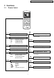
CS-E15DB4EW CU-E15DBE / CS-E18DB4EW CU-E18DBE / CS-E21DB4ES CU-E21DBE 2 Functions 2.1. Remote Control FAN SPEED AUTO HEAT COOL DRY OFF OFF ON TIMER TIMER OFF/ON MODE FAN SPEED POWERFUL AUTO TEMP QUIET AIR SWING MANUAL TIMER ON 1 SET 2 3 CANCEL OFF CHECK CLOCK RESET INVENTER TEMP OFF / ON I Operation OFF / ON MODE Room Temperature Setting • Increase or decrease set temperature.
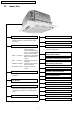
CS-E15DB4EW CU-E15DBE / CS-E18DB4EW CU-E18DBE / CS-E21DB4ES CU-E21DBE 2.2. Indoor Unit Quiet Mode Automatic Operation Switch • To provide quiet operation. • To run automatic operation, force cooling or heating operation, or change remote control signal type. 24-Hour Real Time Timer Control Operation Indication Lamps (LED) • • • • • Automatic Restart Control (Green) ........ Lights up in operation, blinks in Automatic Operation Mode judging, deice, On Timer sampling and Hot Start operation.
CS-E15DB4EW CU-E15DBE / CS-E18DB4EW CU-E18DBE / CS-E21DB4ES CU-E21DBE 2.3.
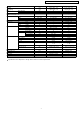
CS-E15DB4EW CU-E15DBE / CS-E18DB4EW CU-E18DBE / CS-E21DB4ES CU-E21DBE 3 Product Specifications 3.1. CS-E15DB4EW CU-E15DBE Unit CS-E15DB4EW CU-E15DBE Cooling Capacity kW kcal/h BTU/h 4.10 (0.90 - 4.80) 3,530 (770 - 4,130) 14,000 (3,070 - 16,400) Heating Capacity kW kcal/h BTU/h 5.10 (0.90 - 6.20) 4,390 (770 - 5,330) 17,400 (3,070 - 21,100) Moisture Removal l/h Pint/h 2.3 (4.
CS-E15DB4EW CU-E15DBE / CS-E18DB4EW CU-E18DBE / CS-E21DB4ES CU-E21DBE Pipe Size (Flare piping) Drain Hose Power Cord Length Number of core-wire Dimensions Inner diameter Length Height Width Depth Net Weight Compressor Motor Rated Air Circulation Motor Fan Speed Heat Exchanger Unit inch inch mm m CS-E15DB4EW G (gas side) ; 1/2” L (liquid side) ; 1/4” 30 0.
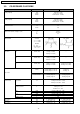
CS-E15DB4EW CU-E15DBE / CS-E18DB4EW CU-E18DBE / CS-E21DB4ES CU-E21DBE 3.2. CS-E18DB4EW CU-E18DBE Unit CS-E18DB4EW CU-E18DBE Cooling Capacity kW kcal/h BTU/h 4.80 (0.90 - 5.70) 4,130 (770 - 4,900) 16,400 (3,070 - 19,400) Heating Capacity kW kcal/h BTU/h 5.60 (0.90 - 7.10) 4,820 (770 - 6,110) 19,100 (3,070 - 24,200) Moisture Removal l/h Pint/h 2.6 (5.
CS-E15DB4EW CU-E15DBE / CS-E18DB4EW CU-E18DBE / CS-E21DB4ES CU-E21DBE Drain Hose Power Cord Length Number of core-wire Dimensions Height Width Depth Net Weight Compressor Motor Rated Air Circulation Motor Fan Speed Heat Exchanger Unit mm m Inner diameter Length CS-E18DB4EW 30 0.
CS-E15DB4EW CU-E15DBE / CS-E18DB4EW CU-E18DBE / CS-E21DB4ES CU-E21DBE 3.3. CS-E21DB4ES CU-E21DBE Unit CS-E21DB4ES CU-E21DBE Cooling Capacity kW kcal/h BTU/h 5.90 (0.90 - 6.30) 5,070 (770 - 5,420) 20,100 (3,070 - 21,500) Heating Capacity kW kcal/h BTU/h 7.00 (0.90 - 8.00) 6,020 (770 - 6,880) 23,900 (3,070 - 27,300) Moisture Removal l/h Pint/h 3.3 (7.
CS-E15DB4EW CU-E15DBE / CS-E18DB4EW CU-E18DBE / CS-E21DB4ES CU-E21DBE Drain Hose Power Cord Length Number of core-wire Dimensions Height Width Depth Net Weight Compressor Motor Rated Air Circulation Motor Fan Speed Heat Exchanger Unit mm m Inner diameter Length inch (mm) inch (mm) inch (mm) lb (kg) Type Type Output Type Material Type Rate Output Lo (Cool/Heat) Me (Cool/Heat) Hi (Cool/Heat) W W rpm rpm rpm Description Tube material Fin material Fin Type Row / Stage FPI Size (W × H × L) Refrigerant
CS-E15DB4EW CU-E15DBE / CS-E18DB4EW CU-E18DBE / CS-E21DB4ES CU-E21DBE 4 Dimensions 4.1. 4.1.1.
CS-E15DB4EW CU-E15DBE / CS-E18DB4EW CU-E18DBE / CS-E21DB4ES CU-E21DBE 4.2. 4.2.1.
CS-E15DB4EW CU-E15DBE / CS-E18DB4EW CU-E18DBE / CS-E21DB4ES CU-E21DBE 5 Refrigeration Cycle Diagram 14
CS-E15DB4EW CU-E15DBE / CS-E18DB4EW CU-E18DBE / CS-E21DB4ES CU-E21DBE 6 Block Diagram 15
CS-E15DB4EW CU-E15DBE / CS-E18DB4EW CU-E18DBE / CS-E21DB4ES CU-E21DBE 7 Wiring Diagram 16
CS-E15DB4EW CU-E15DBE / CS-E18DB4EW CU-E18DBE / CS-E21DB4ES CU-E21DBE 8 Operation Details 8.1. Basic Operation Inverter control, which equipped with a microcomputer in determining the most suitable operating mode as time passes, automatically adjust output power for maximum comfort always. In order to achieve the suitable operation mode, the microcomputer maintains the set temperature by measuring the temperature of environment and performing temperature shifting. 8.1.1.
CS-E15DB4EW CU-E15DBE / CS-E18DB4EW CU-E18DBE / CS-E21DB4ES CU-E21DBE 8.1.2. 8.1.2.1. Cooling Operation Thermostat control • Compressor is OFF when Intake Air Temperature - Internal Setting Temperature < -1.5°C. • Compressor is ON after waiting for 3 minutes, if the Intake Air Temperature - Internal Setting Temperature > Compressor OFF point. 8.1.3. 8.1.3.1. Soft Dry Operation Thermostat control • Compressor is OFF when Intake Air Temperature - Internal Setting Temperature < -2.0°C.
CS-E15DB4EW CU-E15DBE / CS-E18DB4EW CU-E18DBE / CS-E21DB4ES CU-E21DBE 8.1.5. Automatic Operation This mode can be set using remote control and the operation is decided by remote control setting temperature, indoor intake air temperature and outdoor air temperature. During operation mode judgment, indoor fan motor (with speed of Lo-) and outdoor fan motor are running for 30 seconds to detect the indoor intake and outdoor air temperature. The operation mode is decided based on below chart.
CS-E15DB4EW CU-E15DBE / CS-E18DB4EW CU-E18DBE / CS-E21DB4ES CU-E21DBE 8.1.6. Indoor Fan Motor Operation A.
CS-E15DB4EW CU-E15DBE / CS-E18DB4EW CU-E18DBE / CS-E21DB4ES CU-E21DBE 2. Heating ii. Auto Fan Speed 1.
CS-E15DB4EW CU-E15DBE / CS-E18DB4EW CU-E18DBE / CS-E21DB4ES CU-E21DBE 2. Heating Note: a. UP: • If move from Lo, the fan speed will be shifted to Maximum 1520 rpm. • If move from Maximum, the fan speed no change. • In up zone, 10 rpm is added for every 10s until Maximum 1520 rpm. b. DOWN: • The fan speed will be decreased one step every 10 sec. until Minimum 1270 rpm. c. Current Output Fixed: • Maintain at present fan speed. d.
CS-E15DB4EW CU-E15DBE / CS-E18DB4EW CU-E18DBE / CS-E21DB4ES CU-E21DBE D. Deodorizing Control i. Control condition Control at cooling/dry operation and auto fan speed. No Deodorizing Control is performed during ON timer standby operation and during Anti-freezing control prevention. ii. Operation The odor status is arranged as below and it is shifted as follow.
CS-E15DB4EW CU-E15DBE / CS-E18DB4EW CU-E18DBE / CS-E21DB4ES CU-E21DBE 8.1.8. Airflow Direction 1. There are one types of airflow, vertical airflow (directed by horizontal vane). 2. Control of airflow direction can be automatic (angles of direction is determined by operation mode, heat exchanger temperature and intake air temperature) and manual (angles of direction can be adjusted using remote control). 8.1.8.1.
CS-E15DB4EW CU-E15DBE / CS-E18DB4EW CU-E18DBE / CS-E21DB4ES CU-E21DBE C. Control contents 1. Fan speed is changed from normal setting to quiet setting of respective fan speed. This is to reduce sound of Hi, Me, Lo for 3dB. 2. Fan speed for quiet operation is -1 step from setting fan speed. 8.1.9.1. Quiet operation (Heating) A. Purpose To provide quiet heating operation compare to normal operation. B. Control condition a. Quiet operation start condition • When “quiet” button at remote control is pressed.
CS-E15DB4EW CU-E15DBE / CS-E18DB4EW CU-E18DBE / CS-E21DB4ES CU-E21DBE 8.1.10. Powerful Mode Operation When the powerful mode is selected, the internal setting temperature will shift to achieve the setting temperature quickly. (a) Cooling Operation (b) Soft Dry Operation (c) Heating Operation 8.1.11. 24-Hour Real Time Timer Control ON Timer ON timer can be set using remote control, the unit with timer set will start operate earlier than the setting time.
CS-E15DB4EW CU-E15DBE / CS-E18DB4EW CU-E18DBE / CS-E21DB4ES CU-E21DBE 8.1.12. Auto Restart Control 1. When the power supply is cut off during the operation of air conditioner, the compressor will re-operate within three to four minutes (there are 10 patterns between 2 minutes 58 seconds and 3 minutes 52 seconds to be selected randomly) after power supply resumes. 2. This type of control is not applicable during ON/OFF Timer setting. 8.1.13.
CS-E15DB4EW CU-E15DBE / CS-E18DB4EW CU-E18DBE / CS-E21DB4ES CU-E21DBE 8.2. 8.2.1. 8.2.1.1. Protection Control Features Protection Control For All Operations Time Delay Safety Control 1. The compressor will not start for three minutes after stop of operation. 2. This control is not applicable if the power supply is cut off for 20 seconds and on again or after 4-way valve deices condition. 8.2.1.2. 30 Seconds Forced Operation 1.
CS-E15DB4EW CU-E15DBE / CS-E18DB4EW CU-E18DBE / CS-E21DB4ES CU-E21DBE 8.2.1.5. Compressor Overheating Prevention Control Instructed frequency for compressor operation will be regulated by compressor discharge temperature. The changes of frequency are as below figure. 8.2.1.6. Low Pressure Prevention Control (Gas Leakage Detection) a. Control start conditions Control will perform when (1) - (3) condition continues operation for 5 minute and (4) is fulfill. 1.
CS-E15DB4EW CU-E15DBE / CS-E18DB4EW CU-E18DBE / CS-E21DB4ES CU-E21DBE 8.2.2. 8.2.2.1. Protection Control For Cooling & Soft Dry Operation Outdoor Air Temperature Control The compressor operating frequency is regulated in accordance to the outdoor air temperature as shown in the diagram below. This control will begin one minute after the compressor starts. 8.2.2.2. Cooling Overload Control i.
CS-E15DB4EW CU-E15DBE / CS-E18DB4EW CU-E18DBE / CS-E21DB4ES CU-E21DBE 3. Control contents In the outdoor fan speed no. i) In protectorate Domain A is referred to as min 660 rpm. ii) In protectorate Domain B, it is referred to as min 600 rpm. 4. Condition resolutive It is canceled when it stops satisfying all of the above-mentioned. 8.2.2.3. Anti-Freezing Control 1. When indoor heat exchanger temperature is lower than 7°C continuously for six minutes, compressor will stop operating. 2.
CS-E15DB4EW CU-E15DBE / CS-E18DB4EW CU-E18DBE / CS-E21DB4ES CU-E21DBE 8.2.3. 8.2.3.1. Protection Control For Heating Operation Intake Air Temperature Control Compressor will operate at Max freq 94 (E15D), 128 (E18D, E21D) Hz if either one of the below conditions occur: 1. When the indoor intake air temperature is less than 21°C and remote control setting fan speed is lower Me-. 2. When the indoor intake air temperature is 35°C or above. 8.2.3.2.
CS-E15DB4EW CU-E15DBE / CS-E18DB4EW CU-E18DBE / CS-E21DB4ES CU-E21DBE 8.2.3.4. Deice Control • Deice starts to prevent frosting at outdoor heat exchanger. • Deice operation detection commences after minimum 60 minutes of Heating Operation. • The outdoor heat exchanger temperature drops below 3°C for long period (minimum 40 minutes) during compressor is in operation, the deice operation may starts.
CS-E15DB4EW CU-E15DBE / CS-E18DB4EW CU-E18DBE / CS-E21DB4ES CU-E21DBE 9 Operating Instructions 34
CS-E15DB4EW CU-E15DBE / CS-E18DB4EW CU-E18DBE / CS-E21DB4ES CU-E21DBE 35
CS-E15DB4EW CU-E15DBE / CS-E18DB4EW CU-E18DBE / CS-E21DB4ES CU-E21DBE 36
CS-E15DB4EW CU-E15DBE / CS-E18DB4EW CU-E18DBE / CS-E21DB4ES CU-E21DBE 37
CS-E15DB4EW CU-E15DBE / CS-E18DB4EW CU-E18DBE / CS-E21DB4ES CU-E21DBE 38
CS-E15DB4EW CU-E15DBE / CS-E18DB4EW CU-E18DBE / CS-E21DB4ES CU-E21DBE 39
CS-E15DB4EW CU-E15DBE / CS-E18DB4EW CU-E18DBE / CS-E21DB4ES CU-E21DBE 40
CS-E15DB4EW CU-E15DBE / CS-E18DB4EW CU-E18DBE / CS-E21DB4ES CU-E21DBE 41
CS-E15DB4EW CU-E15DBE / CS-E18DB4EW CU-E18DBE / CS-E21DB4ES CU-E21DBE 10 Installation And Servicing Air Conditioner Using R410A 10.1. Outline 10.1.1. About R410A Refrigerant 1. Converting air conditioners to R410A Since it was declared in1974 that chlorofluorocarbons (CFC), hydro chlorofluorocarbons (HCFC) and other substances pose a destructive danger to the ozone layer in the earth´s upper stratosphere (20 to 40 km above the earth), measures have been taken around the world to prevent this destruction.
CS-E15DB4EW CU-E15DBE / CS-E18DB4EW CU-E18DBE / CS-E21DB4ES CU-E21DBE d. R410A refrigerating machine oil Conventionally, mineral oil or a synthetic oil such as alkylbenzene has been used for R22 refrigerating machine oil. Because of the poor compatibility between R410A and conventional oils like mineral oil, however, there is a tendency for the refrigerating machine oil to collect in the refrigerating cycle.
CS-E15DB4EW CU-E15DBE / CS-E18DB4EW CU-E18DBE / CS-E21DB4ES CU-E21DBE 10.2.2. R410A Tools 1. Copper tube gauge for clearance adjustment (used when flaring with the conventional flaring tool (clutch type)) • This gauge makes it easy to set the clearance for the copper tube to 1.0-1.5 mm from the clamp bar of the flaring tool. Fig. 1 Copper tube gauge for clearance adjustment 2.
CS-E15DB4EW CU-E15DBE / CS-E18DB4EW CU-E18DBE / CS-E21DB4ES CU-E21DBE 5. Charging hose • The pressure resistance of the charging hose has been raised to match the higher pressure of R410A. The hose material has also been changed to suit HFC use, and the size of the fitting has been changed to match the manifold ports. Fig. 4 Manifold gauge charging hose Pressure resistance Material Table 8 Difference between R410A and conventional charging hoses Conventional hoses R410A hoses Working pressure 3.
CS-E15DB4EW CU-E15DBE / CS-E18DB4EW CU-E18DBE / CS-E21DB4ES CU-E21DBE 8. Electronic scale for refrigerant charging • Because of the high pressure and fast vaporizing speed of R410A, the refrigerant cannot be held in a liquid phase inside the charging cylinder when charging is done using the charging cylinder method, causing bubbles to form in the measurement scale glass and making it difficult to see the reading.
CS-E15DB4EW CU-E15DBE / CS-E18DB4EW CU-E18DBE / CS-E21DB4ES CU-E21DBE 10.3. Refrigerant Piping Work 10.3.1. Piping Materials It is recommended that you use copper and copper alloy jointless pipes with a maximum oil adherence of 40 mg/10m. Do not use pipes that are crushed, deformed, or discolored (especially the inside surface). If these inferior pipes are used, impurities may clog the expansion valves or capillaries.
CS-E15DB4EW CU-E15DBE / CS-E18DB4EW CU-E18DBE / CS-E21DB4ES CU-E21DBE Nominal diameter Outside diameter (mm) 1/4 3/8 1/2 6.35 9.52 12.70 Nominal diameter Outside diameter (mm) 1/4 3/8 1/2 6.35 9.52 12.70 Table 11 R410A flaring dimensions Wall thickness (mm) R410A flaring tool, clutch type 0.8 0.8 0.8 0 - 0.5 0 - 0.5 0 - 0.5 Table 12 R22 flaring dimensions Wall thickness (mm) R410A flaring tool, clutch type 0.8 0.8 0.8 0 - 0.5 0 - 0.5 0 - 0.
CS-E15DB4EW CU-E15DBE / CS-E18DB4EW CU-E18DBE / CS-E21DB4ES CU-E21DBE b. Copper pipes Use only copper pipes with the thickness given in table 10, and with minimal impurities. Because the surface of the pipe is exposed, you should take special care, and also take measures such as marking the pipes to make sure they are easily distinguished from other piping materials, to prevent mistaken use. 3. Precautions during refrigerant piping work Take the following precautions on-site when connecting pipes.
CS-E15DB4EW CU-E15DBE / CS-E18DB4EW CU-E18DBE / CS-E21DB4ES CU-E21DBE 10.4.2. Transferring (Using New Refrigerant Piping) 1. Removing the unit a. Collecting the refrigerant into the outdoor unit by pumping down The refrigerant can be collected into the outdoor unit (pumping down) by pressing the TEST RUN button, even when the temperature of the room is low. • Check to make sure that the valve stems of the 2-way valve and 3-way valve have been opened by turning them counterclockwise.
CS-E15DB4EW CU-E15DBE / CS-E18DB4EW CU-E18DBE / CS-E21DB4ES CU-E21DBE 10.4.5. Recharging Refrigerant During Servicing When recharging is necessary, insert the specified amount of new refrigerant in accordance with the following procedure. 1. Connect the charging hose to the service port of the outdoor unit. 2. Connect the charging hose to the vacuum pump adaptor. At this time, fully open the 2-way valve and 3-way valve. 3.
CS-E15DB4EW CU-E15DBE / CS-E18DB4EW CU-E18DBE / CS-E21DB4ES CU-E21DBE 10.4.6. Brazing As brazing requires sophisticated techniques and experiences, it must be performed by a qualified person. In order to prevent the oxide film from occurring in the pipe interior during brazing, it is effective to proceed with brazing while letting dry nitrogen gas (N2) flow. 1. Attach a reducing valve to the nitrogen gas cylinder. 2.
CS-E15DB4EW CU-E15DBE / CS-E18DB4EW CU-E18DBE / CS-E21DB4ES CU-E21DBE 11 Installation Instructions 11.1. Safety Precautions • Read the following “SAFETY PRECAUTIONS” carefully before installation. • Electrical work must be installed by a licensed electrician. Be sure to use the correct rating of the power plug and main circuit for the model to be installed. • The caution items stated here must be followed because these important contents are related to safety.
CS-E15DB4EW CU-E15DBE / CS-E18DB4EW CU-E18DBE / CS-E21DB4ES CU-E21DBE CAUTION 1. This equipment must be earthed. It may cause electrical shock if grounding is not perfect. 2. Do not install the unit at place where leakage of flammable gas may occur. In case gas leaks and accumulates at surrounding of the unit, it may cause fire. 3. Carry out drainage piping as mentioned in installation instructions. If drainage is not perfect, water may enter the room and damage the furniture. ATTENTION 1.
CS-E15DB4EW CU-E15DBE / CS-E18DB4EW CU-E18DBE / CS-E21DB4ES CU-E21DBE Attached accessories Applicable piping kit CZ-4F5, 7, 10BP Select the best location OUTDOOR UNIT • If an awning is built over the unit to prevent direct sunlight or rain, be careful that heat radiation from the condenser is not obstructed. • There should not be any animal or plant which could be affected by hot air discharged. • Keep the spaces indicated by arrows from wall, ceiling, fence or other obstacles.
CS-E15DB4EW CU-E15DBE / CS-E18DB4EW CU-E18DBE / CS-E21DB4ES CU-E21DBE * If the height from the floor to ceiling exceeds three meters, air flow distribution deteriorates and the effect is decreased. WARNING 4. The installation position must be able to support a load four times the indoor unit weight. 5. The indoor unit must be away from heat and steam sources, but avoid installing it near an entrance. 6. The indoor unit must allow easy draining. 7.
CS-E15DB4EW CU-E15DBE / CS-E18DB4EW CU-E18DBE / CS-E21DB4ES CU-E21DBE 11.2.2. INSTALLATION OF INDOOR UNIT This air conditioner uses a drain up motor. Horizontally install the unit using a level gauge. CEILING OPENING DIMENSIONS AND HANGING BOLT LOCATION The paper model for installation expand or shrink according to temperature and humidity. Check on dimensions before using it. CAUTION During the installation, care must be taken not to damage electric wires.
CS-E15DB4EW CU-E15DBE / CS-E18DB4EW CU-E18DBE / CS-E21DB4ES CU-E21DBE Vacuum drying After completing the piping connection, execute vacuum drying for the connecting piping and the indoor unit. The vacuum drying must be carried out by using the service ports of both the liquid and gas side valves. CAUTION Use two wrenches and tighten with regular torque ø6.35 mm ø9.52 mm 18 (180) 42 (430) Flare nut fastening torque N·m (kgf·cm) ø12.7 mm 55 (560) ø19.05 mm ø15.88 mm 65 (660) Liquid size piping ø6.
CS-E15DB4EW CU-E15DBE / CS-E18DB4EW CU-E18DBE / CS-E21DB4ES CU-E21DBE 11.2.5. HEAT INSULATION CAUTION Be sure to perform heat insulation on the drain, liquid and gas piping. Imperfection in heat insulation work leads to water leakage. 1. Use the heat insulation material for the refrigerant piping which has an excellent heat-resistance (over 120°C). 2. Precautions in high humidity circumstance.
CS-E15DB4EW CU-E15DBE / CS-E18DB4EW CU-E18DBE / CS-E21DB4ES CU-E21DBE 11.2.6. CONNECTING THE CABLE TO THE INDOOR • Remove the mounting screw, remove the control box cover, and then connect the wires by following the procedure given in the illustration. Earth lead wire shall be longer than other wires as shown in the figure for the electrical safety in case of the slipping out of the cord from anchorage. 11.2.7. INSTALLATION OF DECORATIVE PANEL The decorative panel has its installation direction.
CS-E15DB4EW CU-E15DBE / CS-E18DB4EW CU-E18DBE / CS-E21DB4ES CU-E21DBE 3. Fit the decorative panel and ceiling wall together and confirm no gap in between. Readjust indoor unit height, if there is a gap between ceiling wall and decorative panel. 4. Open the indoor control box cover. (2 pcs) 5. Insert firmly the connector of cosmetic louver to indoor pcb CN-STM1, CN-DISP and CN-STM2. Be caution not to clamp the cord in between control board and control board cover. 6.
CS-E15DB4EW CU-E15DBE / CS-E18DB4EW CU-E18DBE / CS-E21DB4ES CU-E21DBE 11.3. Outdoor Unit 11.3.1. SELECT THE BEST LOCATION (Refer to “Select the best location” section) 11.3.2. INSTALL THE OUTDOOR UNIT • After selecting the best location, start installation according to Indoor/Outdoor Unit Installation Diagram. 1. Fix the unit on concrete or rigid frame firmly and horizontally by bolt nut. (ø10 mm). 2. When installing at roof, please consider strong wind and earthquake.
CS-E15DB4EW CU-E15DBE / CS-E18DB4EW CU-E18DBE / CS-E21DB4ES CU-E21DBE 11.3.4. EVACUATION OF THE EQUIPMENT WHEN INSTALLING AN AIR CONDITIONER, BE SURE TO EVACUATE THE AIR INSIDE THE INDOOR UNIT AND PIPES in the following procedure. 1. Connect a charging hose with a push pin to the Low and High side of a charging set and the service port of the 3-way valve. • Be sure to connect the end of the charging hose with the push pin to the service port. 2.
CS-E15DB4EW CU-E15DBE / CS-E18DB4EW CU-E18DBE / CS-E21DB4ES CU-E21DBE 11.3.5. CONNECT THE CABLE TO THE OUTDOOR UNIT (FOR DETAIL REFER TO WIRING DIAGRAM AT UNIT) 1. Remove the control board cover from the unit by loosening the screw. 2. Connecting cable between indoor unit and outdoor unit shall be approved polychloroprene sheathed 4 × 1.5 mm2 flexible cord, type designation 245 IEC 57 or heavier cord. 3. Secure the cable onto the control board with the holder (clamper). 4.
CS-E15DB4EW CU-E15DBE / CS-E18DB4EW CU-E18DBE / CS-E21DB4ES CU-E21DBE CHANGING THE REMOTE CONTROL TRANSMISSION CODE 1. Press AUTO SW continuously for 11 seconds (buzzer sound = pep pep pep) 2. After 11 seconds, release AUTO SW, then press RemoCon TIMER “ ” SW continuously for 5 seconds. Reset code will be transmitted. After the reset code is transmitted, release TIMER “ ” SW. 3. Press Remo-Con “OFF/ON” button. The new Remo-Con No. will be accepted and memorized, after which the new Remo-Con No.
CS-E15DB4EW CU-E15DBE / CS-E18DB4EW CU-E18DBE / CS-E21DB4ES CU-E21DBE 12 Servicing Information Caution: • Pb free solder has a higher melting point than standard solder; Typically the melting point is 50 - 70°F (30 - 40°C) higher. Please use a high temperature soldering iron. In case of the soldering iron with temperature control, please set it to 700 ± 20°F (370 ± 10°C). • Pb free solder will tend to splash when heated too high (about 1100° F/600°C). 12.1. Troubleshooting 1.
CS-E15DB4EW CU-E15DBE / CS-E18DB4EW CU-E18DBE / CS-E21DB4ES CU-E21DBE 2. Troubleshooting Air Conditioner Refrigeration cycle system In order to diagnose malfunctions, make sure that there are no electrical problems before inspecting the refrigeration cycle. Such problems include insufficient insulation, problem with the power source, malfunction of a compressor and a fan.
CS-E15DB4EW CU-E15DBE / CS-E18DB4EW CU-E18DBE / CS-E21DB4ES CU-E21DBE 1.
CS-E15DB4EW CU-E15DBE / CS-E18DB4EW CU-E18DBE / CS-E21DB4ES CU-E21DBE Error Codes Table Diagnosis display H11 H12 H14 H15 H16 Abnormality / Protection control Abnormality Judgement Emergency operation Primary location to verify • Internal / external cable connections Indoor / outdoor abnormal communication > 1 min after starting Indoor fan operation operation only Connection capability rank abnormal Indoor intake air temperature sensor abnormality Outdoor compressor temperature sensor abnormality O
CS-E15DB4EW CU-E15DBE / CS-E18DB4EW CU-E18DBE / CS-E21DB4ES CU-E21DBE 12.3. Remote Control Remote Control Reset • When the batteries are inserted for the first time or the batteries are replaced, you may notice the indications at remote control’s display screen blink continuously and not functionable. If this condition happens, try to reset the remote control by pushing the reset terminal with a pointing device.
CS-E15DB4EW CU-E15DBE / CS-E18DB4EW CU-E18DBE / CS-E21DB4ES CU-E21DBE 12.4. Auto OFF/ON Button • The “Auto OFF/ON” button is used to operate the air conditioner if remote control is misplaced or malfunctioning. • Auto operation is started once “Auto OFF/ON” button is pressed. • Forced cooling operation is possible by pressing the “Auto OFF/ON” button for more than 5 seconds where “beep” sound is heard, then release the button.
CS-E15DB4EW CU-E15DBE / CS-E18DB4EW CU-E18DBE / CS-E21DB4ES CU-E21DBE 12.5. Disassembly of Parts 1. Open the Intake Grille from the Front Grille by moving the catchers to center (Fig. 1). Fig. 1 2. Remove the Control Board Cover by removing the screws (Fig. 2). 3. Release the (Fig. 3): Fig. 2 • CN-STM1 (WHT) connector. • CN-STM2 (YLW) connector. • CN-DISP (WHT) connector. • CN-FM (WHT) connector. • CN-TH1 (WHT) connector. • CN-TH2 (BLU) connector. • CN-DRMTR1 (BLU) connector.
CS-E15DB4EW CU-E15DBE / CS-E18DB4EW CU-E18DBE / CS-E21DB4ES CU-E21DBE 5. Remove the Front Grille by removing the screw A and screws B, C & D half way open (Fig. 5). Fig. 5 6. Remove the Air Guider and Drain Pan complete by removing the screws (Fig. 6). Fig. 6 7. Remove the Turbo Fan by removing the bolt (Fig. 7). Fig. 7 8. Remove the Fan Motor by release the Fan Motor lead wire connectors and Fan Motor screws (Fig. 8). Fig.
CS-E15DB4EW CU-E15DBE / CS-E18DB4EW CU-E18DBE / CS-E21DB4ES CU-E21DBE Outdoor Electronic Controller Removal Procedure • Be save to return the wiring to its original position 1. Remove the top panel and front panel • There are many high voltage components within the heat sink cover so never touch the interior during operation. Wait at least two minutes after power has been turned off. Fig. 9 2. Remove the Outdoor Electronic Controller Fig. 10 Fig. 11 Fig.
CS-E15DB4EW CU-E15DBE / CS-E18DB4EW CU-E18DBE / CS-E21DB4ES CU-E21DBE 13 Technical Data 13.1. Operation Characteristics 13.1.1.
CS-E15DB4EW CU-E15DBE / CS-E18DB4EW CU-E18DBE / CS-E21DB4ES CU-E21DBE 13.1.2.
CS-E15DB4EW CU-E15DBE / CS-E18DB4EW CU-E18DBE / CS-E21DB4ES CU-E21DBE 13.1.3.
CS-E15DB4EW CU-E15DBE / CS-E18DB4EW CU-E18DBE / CS-E21DB4ES CU-E21DBE 13.2. Sensible Capacity Chart ● CS-E15DB4EW CU-E15DBE Outdoor Temp. (°C) Indoor wet bulb temp. 17.0°C 19.0°C 19.5°C 22.0°C TC 4.07 30 SHC 3.08 IP 1.19 4.46 4.87 3.23 3.35 1.21 1.24 TC 3.80 4.10 4.17 4.55 35 SHC 2.96 3.10 3.22 IP 1.28 1.30 1.31 1.33 TC 3.53 40 SHC 2.84 IP 1.37 TC 3.21 46 SHC 2.70 IP 1.48 3.88 4.23 2.99 3.11 1.40 1.42 3.53 3.85 2.84 2.96 1.51 1.53 TC 4.14 40 SHC 3.33 IP 1.61 TC 3.76 46 SHC 3.
CS-E15DB4EW CU-E15DBE / CS-E18DB4EW CU-E18DBE / CS-E21DB4ES CU-E21DBE 14 Exploded View (Indoor Unit) 14.1.
CS-E15DB4EW CU-E15DBE / CS-E18DB4EW CU-E18DBE / CS-E21DB4ES CU-E21DBE Note: The above exploded view is for the purpose of parts disassembly and replacement. The non-numbered parts are not kept as standard service parts.
CS-E15DB4EW CU-E15DBE / CS-E18DB4EW CU-E18DBE / CS-E21DB4ES CU-E21DBE 14.2. CZ-BT20E (Front Grille Complete) Note: The above exploded view is for the purpose of parts disassembly and replacement. The non-numbered parts are not kept as standard service parts.
CS-E15DB4EW CU-E15DBE / CS-E18DB4EW CU-E18DBE / CS-E21DB4ES CU-E21DBE 15 Replacement Parts List (Indoor Unit) 15.1. CS-E15DB4EW CS-E18DB4EW CS-E21DB4ES REF. NO.
CS-E15DB4EW CU-E15DBE / CS-E18DB4EW CU-E18DBE / CS-E21DB4ES CU-E21DBE 15.2. CZ-BT20E (Front Grille Complete) REF. NO. 1 2 4 5 6 7 8 9 10 11 12 13 14 21 22 24 28 29 PART DESCRIPTION FRONT GRILLE - COMPLETE FRONE - FRONT GRILLE CO. A.S MOTOR DC SINGLE 12V 250 OHM BRACKET - A.S.MOTOR VANE SHAFT SHAFT CONNECTOR - SHAFT BEARING LEAD WIRE - A.S.MOTOR PLATE COVER FOR A.S.MOTOR PLATE COVER FOR CONNECTING SHAFT PLATE COVER FOR END SHAFT ELECTRONIC CONT.
CS-E15DB4EW CU-E15DBE / CS-E18DB4EW CU-E18DBE / CS-E21DB4ES CU-E21DBE 16 Exploded View (Outdoor Unit) 16.1. CU-E15DBE CU-E18DBE CU-E21DBE Note: The above exploded view is for the purpose of parts disassembly and replacement. The non-numbered parts are not kept as standard service parts.
CS-E15DB4EW CU-E15DBE / CS-E18DB4EW CU-E18DBE / CS-E21DB4ES CU-E21DBE 17 Replacement Parts List (Outdoor Unit) 17.1. CU-E15DBE CU-E18DBE CU-E21DBE REF NO.
CS-E15DB4EW CU-E15DBE / CS-E18DB4EW CU-E18DBE / CS-E21DB4ES CU-E21DBE 18 Electronic Circuit Diagram 18.1. Indoor Unit ● CS-E15DB4EW CS-E18DB4EW CS-E21DB4ES SCHEMATIC DIAGRAM 1/4 MAIN ELECTRONIC CONTROLLER INDICATOR COMPLETE IC201 Vout 1 Vcc 2 GND 3 C25 100µ 16V R203 1k R202 47 C26 0.1µ JP5 C202 R03 1k CN-DISP SW201 Auto 1 D205 D204 D203 D202 D201 3 POWER TIMER POWERFUL QUIET AIR SWING F-TEST S-TEST C201 47µF 25V R201 1k 10 1 9 2 8 3 7 4 6 5 5 6 4 7 3 8 2 9 1 10 C02 0.
CS-E15DB4EW CU-E15DBE / CS-E18DB4EW CU-E18DBE / CS-E21DB4ES CU-E21DBE SCHEMATIC DIAGRAM 2/4 SW01 R13 10k C30 0.01µ High Static Pressure c R60 10kΩ 4.7k b C34 0.047µ 25V C35 0.
CS-E15DB4EW CU-E15DBE / CS-E18DB4EW CU-E18DBE / CS-E21DB4ES CU-E21DBE SCHEMATIC DIAGRAM 3/4 T01 A40C1030 O O I C18 100µF 16V NR C16 470µF 25V 5V G 1 I C17 3300µF 35V 12V G 2 DB01 4 3 2 1 2 1 R69 22kΩ 1/4W CN-V2 C13 470µF 63V R05 22kΩ 1/4W C19 L01 C11 0.22µ C33 2 DB03 4 3 R59 7.5Ω 10W CN-T2 1 2 ZNR01 511U C24 SSR01 IC04 1 SSR02 IC03 CN-T1 R61 5.1kΩ FUSE01 T3.
CS-E15DB4EW CU-E15DBE / CS-E18DB4EW CU-E18DBE / CS-E21DB4ES CU-E21DBE SCHEMATIC DIAGRAM 4/4 DRAIN MOTOR DRAIN MOTOR CN-DRMTR2 CN-DRMTR1 1 2 3 3 1 2 4 AC01(BLK) C07 4700p 250VAC C39 100p 250VAC C08 4700p 250VAC R45 6.2k C09 2200p 250VAC R44 6.
CS-E15DB4EW CU-E15DBE / CS-E18DB4EW CU-E18DBE / CS-E21DB4ES CU-E21DBE 18.2. Outdoor Unit ● CU-E15DBE CU-E18DBE CU-E21DBE SCHEMATIC DIAGRAM 1/4 REACTOR GD1 GRY1 GRN ZNR3 ERZV10D102 RY-AC1 C13 4700p 250V C4 C5 ZNR6 ERZVEAV511 ZNR4 ERZVEAV511 C8 1.0µ 250V C7 1.0µ 250V C11 1.
CS-E15DB4EW CU-E15DBE / CS-E18DB4EW CU-E18DBE / CS-E21DB4ES CU-E21DBE SCHEMATIC DIAGRAM 2/4 FUSE2 (T 3.15A L 250V) R111 464k 1/4W 1% R114 464k 1/4W 1% R112 464k 1/4W 1% R115 464k 1/4W 1% T1 ET529AK7NLAC D20 1A5-E 600V R116 10.7k 1/4W 1% R113 11k 1/4W 1% R125 47k 2W C56 56µ 450V R190 7.5Ω 3 5W 2 ZNR5 C57 0.
CS-E15DB4EW CU-E15DBE / CS-E18DB4EW CU-E18DBE / CS-E21DB4ES CU-E21DBE SCHEMATIC DIAGRAM 3/4 C113 0.1µ C117 0.1µ D4 C15 D3 3900p C12 R14 200k C9 3900p D13 HRU0103A2 C21 0.1µ 16V P67/PNM15 P66/PNM14 P65/PNM13 P64/PNM12 P63/PNM11 P62/PNM10 P61 P60 P57/NPNM02 P56/PWN02 P55/NPNM01 P54/PNM01 P53/NPMM00 P52/PMM10 VDD P51/TM1080 VSS P50/TM1010 VDD2 VPP P47/TM10B1 P46/FM10A1 P45/TM9B0 P44/ TM910 P43/ TM9B1 2 3 4 5 6 7 8 R10 1k 9 D2 10 11 C6 0.1µ 16V 12 13 R203 1k 14 15 C124 0.
CS-E15DB4EW CU-E15DBE / CS-E18DB4EW CU-E18DBE / CS-E21DB4ES CU-E21DBE SCHEMATIC DIAGRAM 44 D41 C106 0.47µ 630V Q17 C90 0.047µ 25V P HV1C1 2 1 Vcc IN C84 1000p C92 0.047µ 25V C93 0.047µ 25V C95 0.047µ 25V Vcc IN COM 14 Vcc U OUT IC8 TL3472 IN(Y) 21 IN(X) R182 R184 R186 R192 R194 R187 R191 R193 R176 R185 R174 R177 0.1Ω R180 R172 C103 0.022µ 25V N R183 R167 82.5Ω R175 C101 0.022µ 25V R143 1.40k roc CF0 GND R173 C83 10µ 50V W OUT R170 C99 0.022µ 25V 15 C91 0.
CS-E15DB4EW CU-E15DBE / CS-E18DB4EW CU-E18DBE / CS-E21DB4ES CU-E21DBE How to use electronic circuit diagram TIMER TABLE Name Time 4 way valve abnormality Outdoor air temp. for Hz No. decision Anti-dew formation control Anti-freezing control Thermo OFF delay Low pressure control (gas leakage) compressor OFF time Time delay safety control 4 min. 30 min. 20 min. 6 min. 3 min. 3 min. 2 min. 58 sec. 20 sec. 90 sec. 20 sec. 120 sec. 2 min. 10 sec. 20 sec. 1 hour 120 min. 30 min. 4 min. 30 min.
CS-E15DB4EW CU-E15DBE / CS-E18DB4EW CU-E18DBE / CS-E21DB4ES CU-E21DBE 18.3.
CS-E15DB4EW CU-E15DBE / CS-E18DB4EW CU-E18DBE / CS-E21DB4ES CU-E21DBE 18.4.
CS-E15DB4EW CU-E15DBE / CS-E18DB4EW CU-E18DBE / CS-E21DB4ES CU-E21DBE 18.5.